1-2
12
Connecting the DVD-VCR
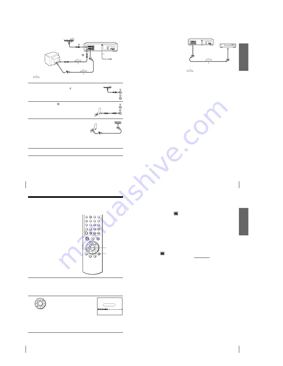
If your TV has a Scart (EURO-AV) connector
1
Disconnect the aerial cable from your
TV and connect it to
on the rear
panel of the DVD-VCR.
2
Connect
of the DVD-VCR and the
aerial input of your TV using the
supplied aerial cable.
3
Connect LINE-1 (EURO AV) on the
DVD-VCR and the Scart (EURO-AV)
connector on the TV with the optional
Scart cable.
This connection improves picture and
sound quality. Whenever you want to
watch the DVD-VCR picture, press
TV/VIDEO to display the VIDEO
indicator in the display window.
4
Connect the mains lead to the mains.
Mains lead
LINE-1
(EURO AV)
AERIAL IN
Scart
(EURO-AV)
to mains
Aerial cable (supplied)
: Signal flow
Scart cable (not supplied)
Getti
ng Sta
rt
ed
13
Connecting the DVD-VCR
Additional connections
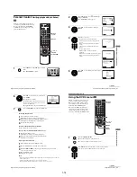
To a satellite or digital tuner
with Line Through
Using the Line Through
function, you can watch
programmes from a satellite or
digital tuner connected to this
DVD-VCR on the TV even
when the DVD-VCR is turned
off. When you turn on the
satellite or digital tuner, this
DVD-VCR automatically sends
the signal from the satellite or
digital tuner to the TV without
turning itself on.
Notes
• This function may not work with some types of satellite or digital tuners.
• When the DVD-VCR is turned off, set the TV to the video channel.
1
Connect the satellite or digital tuner to the LINE-3 connector as shown above.
2
Turn off the DVD-VCR.
To watch a programme, turn on the satellite or digital tuner and the TV.
Scart cable (not supplied)
LINE-3
LINE OUT
: Signal flow
14
Setting up the DVD-VCR with the Auto Set Up function
Step 4 : Setting up the DVD-VCR with the
Auto Set Up function
Before using the DVD-VCR for the first
time, set up the DVD-VCR using the Auto
Set Up function. With this function, you can
set TV channels, guide channels for the
VIDEO Plus+ system, and DVD-VCR clock
automatically.
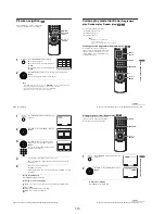
1
Turn on your TV and set it to the video channel.
If your TV does not have a Scart (EURO-AV) connector, tune the TV to
channel 21 (the initial RF channel for this DVD-VCR). Refer to your TV
manual for TV tuning instructions. If the picture does not appear clearly,
see “To change the RF channel” on page 15.
2
Connect the mains lead to the mains.
The DVD-VCR automatically turns on and the
DVD-VCR starts searching for all of the
receivable channels and presets them (in the
appropriate order for your local area).
If you want to change the order of the channels
or disable unwanted programme positions, see
“Changing/disabling programme positions” on page 21.
After the search is complete, the current time appears for any stations that
transmit a time signal. If the time does not appear, set the clock manually.
See “Setting the clock” on page 17.
V/v/B/b
ENTER
O
RETURN
ENTER
RETURN
A U T O S E T U P
P L E A S E W A I T
4 0 %
Getti
ng Sta
rted
15
Setting up the DVD-VCR with the Auto Set Up function
To cancel the Auto Set Up function
Press
O
RETURN.
To change the RF channel
If the picture does not appear clearly on the TV, change the RF channel on the DVD-
VCR and TV. Select
(INSTALLATION) from the menu, then press
V/v
to
select VIDEO OUTPUT CH. Select the RF channel by pressing the
B/b
buttons.
Then, tune the TV to the new RF channel so that a clear picture appears.
Tip
• If you want to change the language for the on-screen display from the one preset in the Auto
Set Up function, see page 16.
Notes
• Whenever you operate the Auto Set Up function, some of the settings (VIDEO Plus+, timer,
etc.) will be reset. If this happens, you have to set them again.
• Auto preset starts automatically only when you plug in the mains lead for the first time after
you purchase the DVD-VCR.
• If you want to use the Auto Set Up function again, press SET UP, then press
V/v/B/b
to
select
(INSTALLATION) and press ENTER. Press
V/v
to select AUTO SET UP.
• Auto preset can be performed by pressing
x
on the DVD-VCR continuously for 5 seconds or
more during power off with no tape inserted.
Содержание SLV-D900E
Страница 38: ...2 8E Fig 2 12 Circuit Board Locations 2 3 Circuit Board Locations VCR MAIN PCB DVD MAIN PCB FUNCTION TIMER PCB ...
Страница 39: ...3 Block Diagram 3 2E 3 1 SLV D900E D900G ...
Страница 40: ...4 PCB Diagrams 4 1 VCR Main 4 3 4 2 DVD Main 4 7 4 3 Function Timer 4 9 4 2 4 1 SLV D900E D900G ...
Страница 41: ...4 3 4 4 4 1 VCR Main COMPONENT SIDE ...
Страница 42: ...4 6 4 5 CONDUCTOR SIDE ...
Страница 43: ...4 7 4 8 4 2 DVD Main CONDUCTOR SIDE COMPONENT SIDE ...
Страница 44: ...4 10E 4 9 4 3 FUNCTION Timer COMPONENT SIDE CONDUCTOR SIDE ...
Страница 47: ...5 6 5 5 5 1 S M P S ...
Страница 48: ...5 8 5 7 FROM TO DVD Audio Video CN4 5 2 Power Drive ...
Страница 49: ...5 10 5 9 5 3 OSD VPS PDS ...
Страница 50: ...5 12 5 11 5 4 NICAM ...
Страница 51: ...5 14 5 13 5 5 A V ...
Страница 52: ...5 16 5 15 5 6 Hi Fi ...
Страница 53: ...5 18 5 17 5 7 Input Output ...
Страница 54: ...5 20 5 19 5 8 TM ...
Страница 55: ...5 22 5 21 5 9 SYSCON ...
Страница 56: ...5 24 5 23 5 10 DVD Main Micom AV Decoder ...
Страница 57: ...5 26 5 25 5 11 DVD Servo ...
Страница 58: ...5 28E 5 27 5 12 DVD Audio Video ...
Страница 60: ...6 2 6 1 2 TEST location for adjustment mode setting TEST SW709 BUTTON Fig 6 2 Function Timer PCB Top View ...


