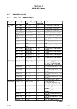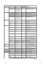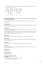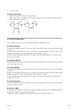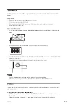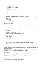
Menu Item
Submenu Item
Choice (Default Set-
ting)
Factory De-
fault Setting
Function
Master Black
-99 to +99
±0
Set the black level of master.
Master Gain (TMP)
-6dB/-3dB/0dB/3dB/6
dB/9dB/12dB/18dB/
24dB/30dB/36dB/
42dB
0 dB
Select the master gain value.
Auto Shading
Auto White Shading
Execute/Cancel
Cancel
Executes the auto white shading function.
Reset White Shading
Execute/Cancel
Cancel
Return to default value.
Auto Black Shading
Execute/Cancel
Cancel
Executes the auto black shading function.
Reset Black Shading
Execute/Cancel
Cancel
Return to default value.
Master Gain (TMP)
-6dB/-3dB/0dB/3dB/6
dB/9dB/12dB/18dB/
24dB/30dB/36dB/
42dB
0 dB
Select the master gain value.
Flare
R Flare
-99 to +99
±0
Adjustment for services of the R-channel
flare correction.
G Flare
-99 to +99
±0
Adjustment for services of the G-channel
flare correction.
B Flare
-99 to +99
±0
Adjustment for services of the B-channel
flare correction.
RPN
APR
Execute/Cancel
Cancel
Execute the auto fault correction (Auto
pixel noise reduction).
Channel
R/G/B
R
Select and display the channel (color) of
the RPN correction.
Cursor
On/Off
Off
Turns On or Off the RPN correction point
indicator cursor.
Cursor H Position
1 to 1950
975
Displays and move the horizontal address
of the RPN correction point indicator cur-
sor.
Cursor V Position
1 to 1094
547
Displays and move the vertical address of
the RPN correction point indicator cur-
sor.
Cursor Next
—
—
Moves the RPN correction point indica-
tor cursor to the next RPN point.
Cursor Prev
—
—
Moves the RPN correction point indica-
tor cursor to the previous RPN point.
Record
Execute/Cancel
Cancel
Registers the RPN.
Delete
Execute/Cancel
Cancel
Deletes the RPN.
Reset
Execute/Cancel
Cancel
Deletes all the RPN that are registered
after shipment from the factory.
Knee
Blue Knee Satura-
tion
0/-1/-2/-3/-4
0
Weaken the Blue Knee Saturation effec-
tive, Blue Fringe is made inconspicuous.
VCO Adjust-
ment
Clock Out Select
On/Off
Off
Outputs the master-clock from the TEST
OUT connector.
Clock Frequency
-99 to +99
±0
Master-clock frequency adjustment.
Fan Control
Fan Control Mode
Normal/Max/Min/Off
Normal
Fan control mode setting.
Factory Reset
Reset
Execute/Cancel
Cancel
Execute a factory reset.
Password Reset
Reset
Execute/Cancel
Cancel
Execute a password reset.
Information
Serial Number
xxxxxx (Display only)
(Display only)
Shows the serial number
Imager Temperature
xx
℃
(Display only)
(Display only)
Displays the temperature of the image
sensor
Main Board Tem-
perature
xx
℃
(Display only)
(Display only)
Displays the internal temperature
(around main board)
Net-Func Log Dump
Execute/Cancel
Cancel
Save the log of the Wireless Module
Continued
PXW-X500
4-2
Содержание PXW-X500
Страница 1: ...SOLID STATE MEMORY CAMCORDER PXW X500 SERVICE MANUAL 1st Edition ...
Страница 4: ......
Страница 8: ......
Страница 10: ......
Страница 39: ...4 Set the date and time of the internal clock Refer to the operating instructions PXW X500 1 29 ...
Страница 54: ......
Страница 87: ...3 Remove the tape AS Tape AS PXW X500 2 33 ...
Страница 107: ...2 Remove the two screws and draw the duct box assembly PSW2 x 5 PSW2 x 5 Duct box assembly PXW X500 2 53 ...
Страница 109: ...4 Install the removed parts by reversing the steps of removal PXW X500 2 55 ...
Страница 158: ......
Страница 183: ......
Страница 184: ...PXW X500 SY PXW X500 CN J E 9 878 582 01 Sony Corporation Printed in Japan 2014 11 08 2014 ...


