


TVP-21
94
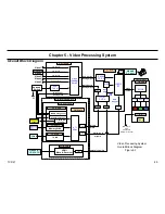
6. Audio Processing System
Overall System Description
Reference Figures 6-1
All audio inputs are routed through
IC507 (Analog Audio Switch)
on the
ASU-Board. The only audio inputs not applied directly to the ASU-Board
and IC507 are as follows.
•
Audio Input 2
•
NTSC Tuner
•
ATSC Tuner
•
Memory Stick
•
i-Link
•
HDMI or DVI
Audio Input 2 is first applied to the H3- Board and then to the ASU-Board
and IC507.
The NTSC and ATSC tuners are located in the Q-Box module. Notice
that the ATSC tuner audio passes through the NTSC tuner. The single
tuner audio output from the Q-Box module passes through the DSU-
Board before being applied to the ASU-Board and IC507.
Memory Stick and i-Link are also located in the Q-Box module. The
audio for these two sources is first applied to the ATI microprocessor, and
the single output is D/A (digital to analog) converter. The resulting analog
single passes through the DSU-Board before being applied to the ASU-
Board and IC507.
The analog switcher IC507 single output (analog audio single) is applied
to an A/D 9analog to digital) converter. The output digital signal is in
the SPDIF (Sony/Phillips Digital Interface). The ASU-Board sends the
SPDIF signal to the AK-Board.
IC2600 on the AK-Board performs the SPDIF to IIS conversion. The IIS
digital signal is a PCM type digital audio format.
The IIS single is then applied to the K-Board where the S-Master digital
audio amplifier system is located. IC3009 performs the IIS to PWM
conversion. The PWM signal is then applied to IC3005 where it is
amplifier before being applied to the Low-Pass output filter. The Low-
Pass filter converts the PWM signal into an analog audio signal, which is
finally applied to the speakers.
Содержание KDS-R60XBR1 - 60" Rear Projection TV
Страница 1: ...Models KDS R50XBR1 KDS R60XBR1 Diagnostics and Troubleshooting Course TVP 21 Training Manual ...
Страница 49: ...TVP 21 46 Disassembly Procedures Wire Routing Diagrams Wire Routing Diagrams ...
Страница 50: ...TVP 21 47 Disassembly Procedures Wire Routing Diagrams cont ...
Страница 51: ...TVP 21 48 Disassembly Procedures Wire Routing Diagrams cont ...
Страница 52: ...TVP 21 49 Disassembly Procedures Wire Routing Diagrams cont ...
Страница 53: ...TVP 21 50 Disassembly Procedures Wire Routing Diagrams cont ...
Страница 58: ...TVP 21 55 Chapter 2 Initial Contact Analysis ...
Страница 72: ...TVP 21 69 4 Protection Circuits Troubleshooting Flowcharts Flowchart C 1 Figure 4 2 ...
Страница 73: ...TVP 21 70 4 Protection Circuits Flowchart C 2 Figure 4 3 ...
Страница 74: ...TVP 21 71 4 Protection Circuits Flowchart C 3 Figure 4 4 ...
Страница 75: ...TVP 21 72 4 Protection Circuits Flowchart C 4 Figure 4 5 ...
Страница 87: ...TVP 21 84 5 Video Processing System No Video Flowchart D Figure 5 2 Troubleshooting Flowcharts ...
Страница 88: ...TVP 21 85 5 Video Processing System Video Distortion Flowchart E Figure 5 3 ...
Страница 89: ...TVP 21 86 5 Video Processing System Optical Block Flowchart F Figure 5 4 ...
Страница 98: ...TVP 21 95 6 Audio Processing System Troubleshooting Flowchart ...
Страница 102: ...TVP 21 99 Appendix 2005 SXRD Service Mode Options ...