


TVP-21
81
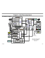
5. Video Processing System
Overall System Description
Reference Figure 5-1
The 2005 SXRD model includes the following video input sources.
•
Video 1, 2, 3
Video 1, 2, 3 are all three-wire cable inputs with the
Yellow
RCA jack
transporting all the video information (Synchronization and Color
information) and the
Red and White
transporting left and right audio
information.
Typical external devices are the VCR, DVD, and A/V Receiver units.
•
Video 4, 5
Video 4, 5 are both three-wire (Video) cable and separate two-wire
(Audio) cable inputs. The three-wire
(Red, Green, & Blue or RGB)
cable transports the separate Red, Green, and Blue video information.
A separate two-wire cable
(Red and White)
transports the left and
right audio information for each input.
Typical external devices are the DVD, DVR, Satellite Receivers units.
•
Video 6, 7
Video 6, 7 are both complete digital video (and audio in the case
of HDMI) input sources. The 2005 SXRD models accept both
High-Definition Multimedia Interface or HDMI (Video & Audio) and
Digital Visual Interface or DVI (Video Only) input sources. The DVI
connection needs a DVI-to-HDMI adaptor in order to connect to the
HDMI connector input.
Typical external devices are the DVD, DVR, Satellite Receivers, A/V
Receiver, and Set-Top-Box units.
•
Video 8
Video 8 connects directly to a Personal Computer or PC monitor
output source using a HD15 or SVGA cable. The input accepts VGA,
SVGA, XGA, WXGA, and SXGA resolution signals from the PC. A
separate Stereo Mini Plug transports the audio for the PC input.
•
RF Inputs
o
NTSC Main Analog Tuner
This tuner receives and demodulates all analog CATV and
Over-the-Air broadcast signals.
o
NTSC Sub Analog Tuner
This tuner receives and demodulates all analog CATV and
Over-the-Air broadcast signals. This tuner is used in multi-
panel display such as, Twin-View and Favorites display
modes.
o
ATSC Digital Tuner
This tuner receives and demodulates all digital
(Unscrambled
or In-the-Clear)
CATV and Over-the-Air broadcast signals.
This tuner is used in multi-panel display such as, Twin-View
and Favorites display modes.
•
CableCard
The CableCard is used in conjunction with the ATSC Digital Tuner to
receive and demodulate
(Scrambled or Premium)
CATV and Over-
the-Air broadcast signals. The CableCard is purchased from the local
cable service provider and is programmed for the particular channel
package purchased by the customer.
Содержание KDS-R60XBR1 - 60" Rear Projection TV
Страница 1: ...Models KDS R50XBR1 KDS R60XBR1 Diagnostics and Troubleshooting Course TVP 21 Training Manual ...
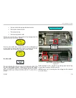
Страница 49: ...TVP 21 46 Disassembly Procedures Wire Routing Diagrams Wire Routing Diagrams ...
Страница 50: ...TVP 21 47 Disassembly Procedures Wire Routing Diagrams cont ...
Страница 51: ...TVP 21 48 Disassembly Procedures Wire Routing Diagrams cont ...
Страница 52: ...TVP 21 49 Disassembly Procedures Wire Routing Diagrams cont ...
Страница 53: ...TVP 21 50 Disassembly Procedures Wire Routing Diagrams cont ...
Страница 58: ...TVP 21 55 Chapter 2 Initial Contact Analysis ...
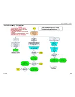
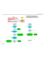
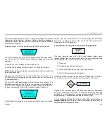
Страница 72: ...TVP 21 69 4 Protection Circuits Troubleshooting Flowcharts Flowchart C 1 Figure 4 2 ...
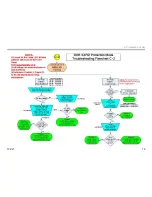
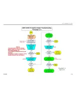
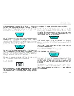
Страница 73: ...TVP 21 70 4 Protection Circuits Flowchart C 2 Figure 4 3 ...
Страница 74: ...TVP 21 71 4 Protection Circuits Flowchart C 3 Figure 4 4 ...
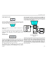
Страница 75: ...TVP 21 72 4 Protection Circuits Flowchart C 4 Figure 4 5 ...
Страница 87: ...TVP 21 84 5 Video Processing System No Video Flowchart D Figure 5 2 Troubleshooting Flowcharts ...
Страница 88: ...TVP 21 85 5 Video Processing System Video Distortion Flowchart E Figure 5 3 ...
Страница 89: ...TVP 21 86 5 Video Processing System Optical Block Flowchart F Figure 5 4 ...
Страница 98: ...TVP 21 95 6 Audio Processing System Troubleshooting Flowchart ...
Страница 102: ...TVP 21 99 Appendix 2005 SXRD Service Mode Options ...