


TVP-21
26
Disassembly Procedures
Screws
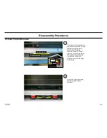
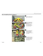
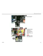
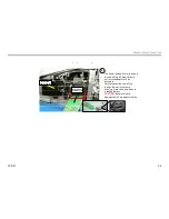
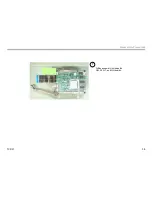
Rear and Sub Plastic Cover Removal & ASU-Board Access
1
Remove 9 screws and pull rear
plastic cover straight back and
off.
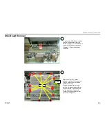
Detach
AC Cord
2
Remove 5 screws and detach
AC cord from the slot. Pull sub
plastic cover
slowly
straight
back and off.
NOTE:
Be careful of fan wire
and connector behind sub-
cover. Disconnect fan cable to
completely remove cover.
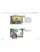
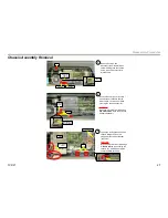
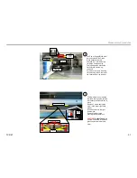
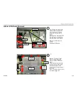
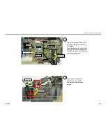
Screws
Shields
Screws
Release Wire Tie
Bracket
3
Remove 4 screws and release
the one wire tie. Slide the
bracket up slightly and pull off.
Disconnect the S1-Board
Remove both shields to access
the ASU-Board.
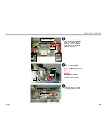
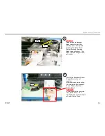
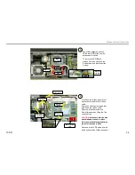
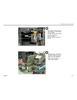
CN2006
CN2010
CN2100
4
The ASU-Board can be probed
for troubleshooting at this point
of the disassembly process. It
can not be remove at this point .
Reference “ASU & G-Board
Removal” section.
S1-Board
Disconnect
fan cable
behind cover
Rear & Sub Plastic Cover Removal
Содержание KDS-R60XBR1 - 60" Rear Projection TV
Страница 1: ...Models KDS R50XBR1 KDS R60XBR1 Diagnostics and Troubleshooting Course TVP 21 Training Manual ...
Страница 49: ...TVP 21 46 Disassembly Procedures Wire Routing Diagrams Wire Routing Diagrams ...
Страница 50: ...TVP 21 47 Disassembly Procedures Wire Routing Diagrams cont ...
Страница 51: ...TVP 21 48 Disassembly Procedures Wire Routing Diagrams cont ...
Страница 52: ...TVP 21 49 Disassembly Procedures Wire Routing Diagrams cont ...
Страница 53: ...TVP 21 50 Disassembly Procedures Wire Routing Diagrams cont ...
Страница 58: ...TVP 21 55 Chapter 2 Initial Contact Analysis ...
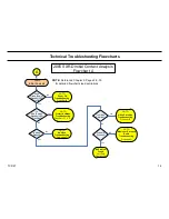
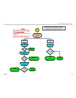
Страница 72: ...TVP 21 69 4 Protection Circuits Troubleshooting Flowcharts Flowchart C 1 Figure 4 2 ...
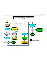
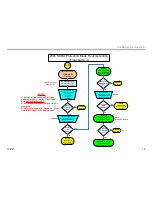
Страница 73: ...TVP 21 70 4 Protection Circuits Flowchart C 2 Figure 4 3 ...
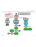
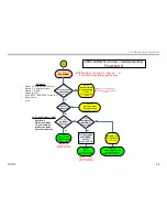
Страница 74: ...TVP 21 71 4 Protection Circuits Flowchart C 3 Figure 4 4 ...
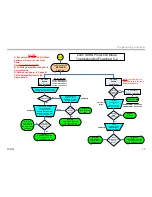
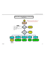
Страница 75: ...TVP 21 72 4 Protection Circuits Flowchart C 4 Figure 4 5 ...
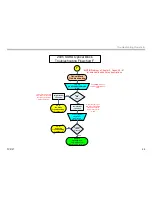
Страница 87: ...TVP 21 84 5 Video Processing System No Video Flowchart D Figure 5 2 Troubleshooting Flowcharts ...
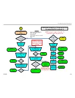
Страница 88: ...TVP 21 85 5 Video Processing System Video Distortion Flowchart E Figure 5 3 ...
Страница 89: ...TVP 21 86 5 Video Processing System Optical Block Flowchart F Figure 5 4 ...
Страница 98: ...TVP 21 95 6 Audio Processing System Troubleshooting Flowchart ...
Страница 102: ...TVP 21 99 Appendix 2005 SXRD Service Mode Options ...