


TVP-21
52
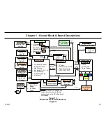
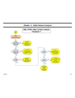
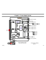
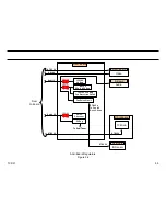
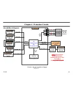
1. Overall System Block
PCB and Module Descriptions
F-Board (Power Supply)
The F-Board is the board connected directly to the AC outlet through the
AC power cord, and includes the following components and circuits.
•
AC Main Fuse
•
AC Line Filter Circuit
G-Board Power Supply)
Except some regulator circuits on various boards, the G-Board is the
power supply system board, which includes the following components
and circuits.
•
Standby 5V Power Supply
o
5V
•
Main Power Supply
o
11V
o
16.5V
o
Thru 5V
o
6.5V
o
Switched 9V
o
380V
•
Power Factor Circuit (PFC)
•
Main AC Relay
•
Inrush Current Relay
Lamp Power Supply Block (aka Ballast, Lamp Driver)
The 380V volts developed in the Main Power Supply on the G-Board powers
the Lamp Power Supply Block. The Lamp Power develops approximately
12K voltages to initial ignite the High Voltage Mercury Vapor Arc Lamp.
After the initial high voltage the Lamp Power Supply Block regulates the
lamp voltage down to approximately 60V during normal operation. The
lamp voltage must be strictly regulated to keep the current in the Lamp
from running away and destroying the lamp.
ASU-Board (Audio/Video Switching, System Control,
& Audio Processing)
The ASU-Board performs all the analog video and audio switching
functions. The following video and audio inputs are switched on this
board.
Video:
•
Video Inputs 1, 2, 3 (Composite)
•
Video Inputs 4, 5 (Component)
•
NTSC Main Analog Tuner
•
NTSC Sub Analog Tuner
NOTE:
Video inputs from the Q-Box module (ATSC Tuner, i-Link, Memory
Stick, and HDMI) go directly to the DSU-Board. In addition, the PC Input
goes to the DSU-Board.
Audio:
All audio inputs are switched on the ASU-Board.
The following circuits are also located on the ASU-Board.
•
DE Microprocessor
•
Fan Driver Circuits
•
Audio Processor
•
Control S Input
Содержание KDS-R60XBR1 - 60" Rear Projection TV
Страница 1: ...Models KDS R50XBR1 KDS R60XBR1 Diagnostics and Troubleshooting Course TVP 21 Training Manual ...
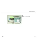
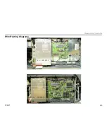
Страница 49: ...TVP 21 46 Disassembly Procedures Wire Routing Diagrams Wire Routing Diagrams ...
Страница 50: ...TVP 21 47 Disassembly Procedures Wire Routing Diagrams cont ...
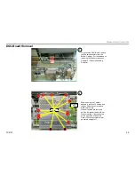
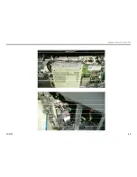
Страница 51: ...TVP 21 48 Disassembly Procedures Wire Routing Diagrams cont ...
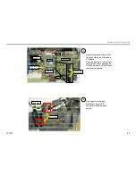
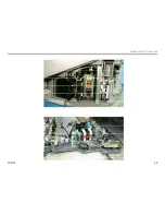
Страница 52: ...TVP 21 49 Disassembly Procedures Wire Routing Diagrams cont ...
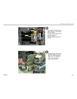
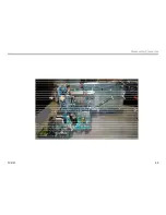
Страница 53: ...TVP 21 50 Disassembly Procedures Wire Routing Diagrams cont ...
Страница 58: ...TVP 21 55 Chapter 2 Initial Contact Analysis ...
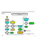
Страница 72: ...TVP 21 69 4 Protection Circuits Troubleshooting Flowcharts Flowchart C 1 Figure 4 2 ...
Страница 73: ...TVP 21 70 4 Protection Circuits Flowchart C 2 Figure 4 3 ...
Страница 74: ...TVP 21 71 4 Protection Circuits Flowchart C 3 Figure 4 4 ...
Страница 75: ...TVP 21 72 4 Protection Circuits Flowchart C 4 Figure 4 5 ...
Страница 87: ...TVP 21 84 5 Video Processing System No Video Flowchart D Figure 5 2 Troubleshooting Flowcharts ...
Страница 88: ...TVP 21 85 5 Video Processing System Video Distortion Flowchart E Figure 5 3 ...
Страница 89: ...TVP 21 86 5 Video Processing System Optical Block Flowchart F Figure 5 4 ...
Страница 98: ...TVP 21 95 6 Audio Processing System Troubleshooting Flowchart ...
Страница 102: ...TVP 21 99 Appendix 2005 SXRD Service Mode Options ...