


TVP-21
92
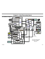
5. Video Processing System
The opposite of the previous conclusion is true if the video distortion
appears on the ATSC Tuner and Memory Stick inputs but not on the
Video 1, 2, 3. In this case, the defect would most likely exist in the Q-Box
module. The reason for this conclusion relies on the fact that Video 1, 2,
and 3 travels completely through the ASU/DSU Assembly and there is no
distortion. This provides a strong indication that the ASU/DSU Assembly
is functioning properly. The fact that the majority of the ASTC Tuner and
Memory Stick signal path is through the Q-Box module and the signal
is distorted provides strong evidence that the defect exists in the Q-Box
module.
The same deductive reasoning can be applied when troubleshooting video
defects using the other video inputs shown on the flowchart. This method
simple involves knowing the path the input signal must take through the
video processing system to reach the display. With this knowledge you
can effectively divide the video system into distinct areas, and therefore,
isolate the defect.
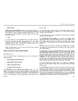
Optical Block
Optical Block
Troubleshooting
The primary objective of this troubleshooting flowchart is to determine if
the Optical Block, Video Circuits, or the Power Supply System is causing
the abnormal TV operation. The very first step is to eliminate or confirm
the Optical Block as the defect component. The quickest and surest way
to confirm proper Optical Block operation is to access and display the
ROOK test patterns.
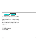
Turn ON
PANEL SERVICE MODE
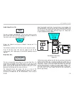
Internal Signal Generator
Because the ROOK IC7701 (located on the C-Board) generates the
test patterns, the patterns are applied directly to the LCD drive IC’s and
LCD panels bypassing all other video processing circuits. Therefore, the
Optical Block is isolated for troubleshooting purposes. If the patterns are
displayed then the Optical Block is OK and the video processing circuits
need to be examined.
Dark Raster
is Displayed
The next step is to check the raster intensity (or Overall LCD Panel
Lighting) when the ROOK test patterns are turned off and the TV is in
normal display mode. If the raster is dark, then this indicates no drive
to the LCD panels and you should go to the No Video Troubleshooting
Flowchart D to check the video processing circuits.
Bright Raster
is Displayed
On the other hand, if the test patterns do not display and the raster is
bright white, then the LCD panels are receiving drive signals from the
LCD drivers. However, no video is reaching the LCD panels. Therefore,
the next step is to check the power supply to the C-Board video circuits.
Check Voltage at
CN7954/pin 1
DSU--Board
The voltage at CN7954/pin 1 on the DSU-Board should be 16.5V. If
the voltage is missing then you need to troubleshoot the power supply
system, go to Power On Troubleshooting Flowchart B. The Main Power
Supply develops the 16.5V.
If the 16.5V is present then the defect exists on the C-Board. In this case,
replace the Optical Block because the C-Board comes as part of Optical
Block assembly.
Содержание KDS-R60XBR1 - 60" Rear Projection TV
Страница 1: ...Models KDS R50XBR1 KDS R60XBR1 Diagnostics and Troubleshooting Course TVP 21 Training Manual ...
Страница 49: ...TVP 21 46 Disassembly Procedures Wire Routing Diagrams Wire Routing Diagrams ...
Страница 50: ...TVP 21 47 Disassembly Procedures Wire Routing Diagrams cont ...
Страница 51: ...TVP 21 48 Disassembly Procedures Wire Routing Diagrams cont ...
Страница 52: ...TVP 21 49 Disassembly Procedures Wire Routing Diagrams cont ...
Страница 53: ...TVP 21 50 Disassembly Procedures Wire Routing Diagrams cont ...
Страница 58: ...TVP 21 55 Chapter 2 Initial Contact Analysis ...
Страница 72: ...TVP 21 69 4 Protection Circuits Troubleshooting Flowcharts Flowchart C 1 Figure 4 2 ...
Страница 73: ...TVP 21 70 4 Protection Circuits Flowchart C 2 Figure 4 3 ...
Страница 74: ...TVP 21 71 4 Protection Circuits Flowchart C 3 Figure 4 4 ...
Страница 75: ...TVP 21 72 4 Protection Circuits Flowchart C 4 Figure 4 5 ...
Страница 87: ...TVP 21 84 5 Video Processing System No Video Flowchart D Figure 5 2 Troubleshooting Flowcharts ...
Страница 88: ...TVP 21 85 5 Video Processing System Video Distortion Flowchart E Figure 5 3 ...
Страница 89: ...TVP 21 86 5 Video Processing System Optical Block Flowchart F Figure 5 4 ...
Страница 98: ...TVP 21 95 6 Audio Processing System Troubleshooting Flowchart ...
Страница 102: ...TVP 21 99 Appendix 2005 SXRD Service Mode Options ...