


TVP-21
75
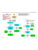
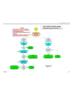
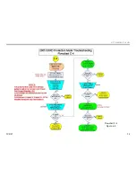
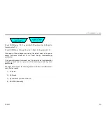
4. Protection Circuits
•
The door tab which depresses the detector switch
•
The lamp door detector switch
•
The lamp power plug
•
The lamp plug detector switch
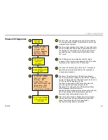
If the door, door switch, lamp, or lamp switch are found damaged then the
appropriate component must be replaced.
Replace T1 or T3
Board(s)
(T1) A-1123-096-A
(T3) A-1144-528-A
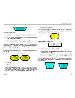
If the door, door switch, lamp, or lamp switch are found undamaged and
all connections are secure then there must be a problem with the DE
microprocessor and the ASU/DSU assembly must be replaced).
Replace
ASU/DSU Assembly
50" A-1152-715-A
60" A-1152-714-A
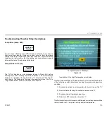
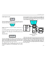
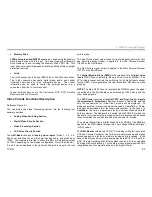
Fan Error (4X)
4X Flash
Pattern
(Fan Rotation )
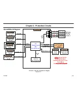
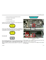
The main objective when this error occurs is to determine which of the
four fans have stopped rotating. Visually check the two-rear exhaust
(Fans 1 & 4, Reference Figure 4-7 for fan locations) fans first for rotation.
Both fans should begin rotating immediately after the TV power button is
pressed.
Check rear fans (1 & 4 ) that are
visually accessible
for rotation
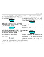
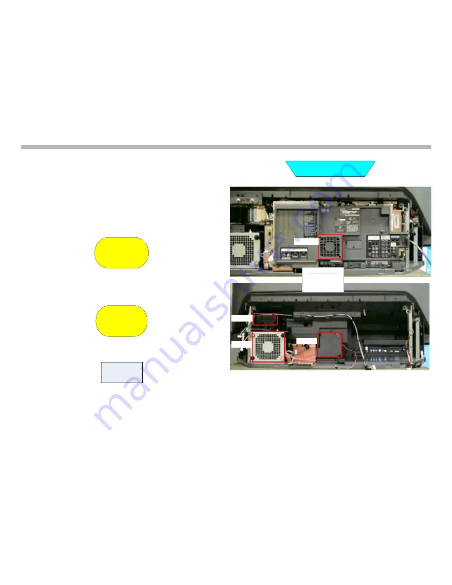
FAN #4
FAN #1
FAN #2
FAN #3
Fan Part Numbers
Fan #1 – 8-835-860-11
Fan #2 – 8-835-859-11
Fan #3 – 8-835-859-11
Fan #4 – 1-787-333-11
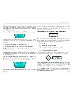
Before replacing Fan #1 or Fan #4 for non-rotating check that the fans
drive voltage is present at CN2301/pins 2 &11.
NOTE:
Because the TV is shutting down the voltages must be measured
prior to shut down.
Fan Location & Numbering Diagram
Figure 4-7
Содержание KDS-R60XBR1 - 60" Rear Projection TV
Страница 1: ...Models KDS R50XBR1 KDS R60XBR1 Diagnostics and Troubleshooting Course TVP 21 Training Manual ...
Страница 49: ...TVP 21 46 Disassembly Procedures Wire Routing Diagrams Wire Routing Diagrams ...
Страница 50: ...TVP 21 47 Disassembly Procedures Wire Routing Diagrams cont ...
Страница 51: ...TVP 21 48 Disassembly Procedures Wire Routing Diagrams cont ...
Страница 52: ...TVP 21 49 Disassembly Procedures Wire Routing Diagrams cont ...
Страница 53: ...TVP 21 50 Disassembly Procedures Wire Routing Diagrams cont ...
Страница 58: ...TVP 21 55 Chapter 2 Initial Contact Analysis ...
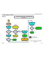
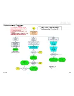
Страница 72: ...TVP 21 69 4 Protection Circuits Troubleshooting Flowcharts Flowchart C 1 Figure 4 2 ...
Страница 73: ...TVP 21 70 4 Protection Circuits Flowchart C 2 Figure 4 3 ...
Страница 74: ...TVP 21 71 4 Protection Circuits Flowchart C 3 Figure 4 4 ...
Страница 75: ...TVP 21 72 4 Protection Circuits Flowchart C 4 Figure 4 5 ...
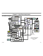
Страница 87: ...TVP 21 84 5 Video Processing System No Video Flowchart D Figure 5 2 Troubleshooting Flowcharts ...
Страница 88: ...TVP 21 85 5 Video Processing System Video Distortion Flowchart E Figure 5 3 ...
Страница 89: ...TVP 21 86 5 Video Processing System Optical Block Flowchart F Figure 5 4 ...
Страница 98: ...TVP 21 95 6 Audio Processing System Troubleshooting Flowchart ...
Страница 102: ...TVP 21 99 Appendix 2005 SXRD Service Mode Options ...