

TVP-21
61
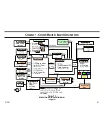
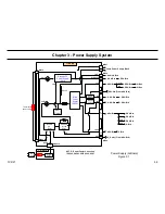
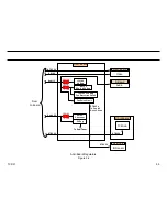
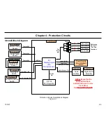
3. Power Supply System
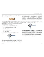
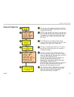
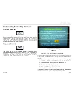
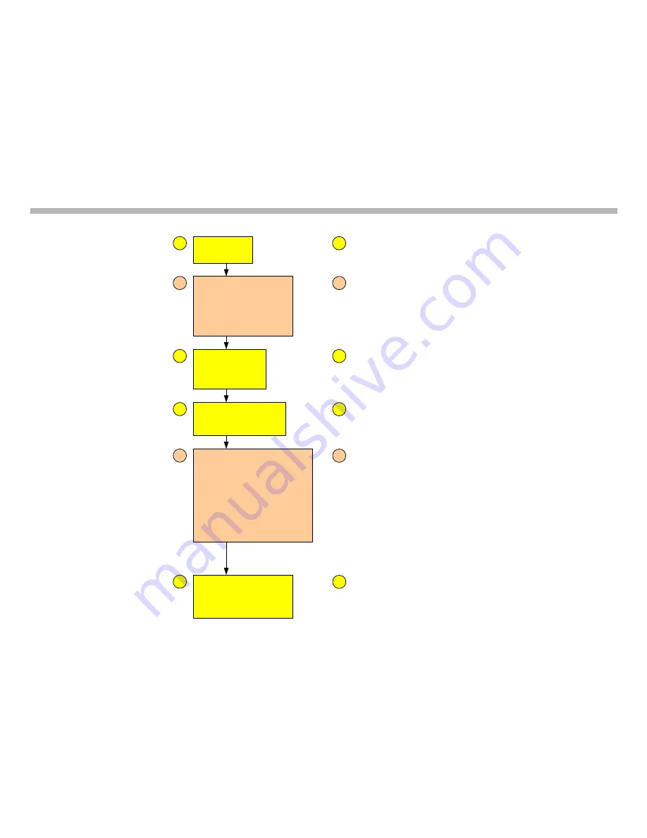
Power-ON Sequence
AC Power
Applied
Standby 5V -
ON
AC Relay -
OFF
TV Micro -
Standby
IR Sensor –
ON
PFC Circuit -
ON
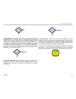
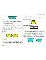
“ON” Command
Receicve
(TV Micro)
“AC-RELAY” -
HIGH
“REC-ON” -
HIGH
AC Relay –
ON
IC6401 SW9V –
ON
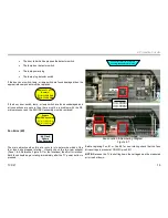
Main Power Supply –
ON
InRush Relay –
ON
I2C Microprocessor
communications -
Active
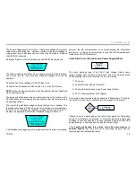
Green
(Power/Standby)LED
Flashes
Green (Power/Standby)
LED Glows Steady
(Unit ON)
1
2
3
4
5
6
1
2
3
4
5
6
The AC power cord is plugged into the AC outlet and the
AC voltage passes through F-Board (Main Fuse OK) and
is applied to the G-Board.
The AC voltage supplied to the G-board is applied directly
to the AC-Relay and the Standby 5V power supply circuit.
The Standby 5V is applied to the TV Micro and places it
into standby mode. It also turns ON the IR sensor and
PFC circuit.
The TV-Microprocessor located on the DSU-Board
receives a ON command when either the ON /OFF button
is pressed on the remote or the TV front panel .
The Green (Power/Standby) LED on the TV front panel
begins flashing immediately after the ON command is
received and processed.
The Green (Power/Standby) LED continues flashing.
The TV microprocessor sends the “AC-RELAY” signal to
turn the AC Relay ON, and “REC-ON” signal, which is the
VCC for the SW9V Regulator IC6401.
The Main Power Supply IC6301 turns ON and all the
television operating voltages are developed.
Regulated 5V is fed back to turn ON the InRush Relay ,
which bypasses the InRush resistor.
Operational acknowledgments are sent and received over
the I2C bus between all microprocessors and other
devices such as the temperature sensor ICs .
After all the power supply voltages and microprocessor
communications have been successfully develop the
Green (Power/Standby) LED will glow steady.
The Power-ON sequence is completed.
Содержание KDS-R60XBR1 - 60" Rear Projection TV
Страница 1: ...Models KDS R50XBR1 KDS R60XBR1 Diagnostics and Troubleshooting Course TVP 21 Training Manual ...
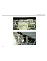
Страница 49: ...TVP 21 46 Disassembly Procedures Wire Routing Diagrams Wire Routing Diagrams ...
Страница 50: ...TVP 21 47 Disassembly Procedures Wire Routing Diagrams cont ...
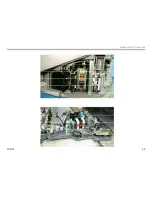
Страница 51: ...TVP 21 48 Disassembly Procedures Wire Routing Diagrams cont ...
Страница 52: ...TVP 21 49 Disassembly Procedures Wire Routing Diagrams cont ...
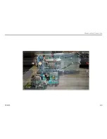
Страница 53: ...TVP 21 50 Disassembly Procedures Wire Routing Diagrams cont ...
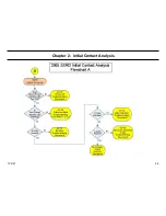
Страница 58: ...TVP 21 55 Chapter 2 Initial Contact Analysis ...
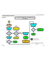
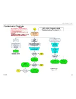
Страница 72: ...TVP 21 69 4 Protection Circuits Troubleshooting Flowcharts Flowchart C 1 Figure 4 2 ...
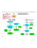
Страница 73: ...TVP 21 70 4 Protection Circuits Flowchart C 2 Figure 4 3 ...
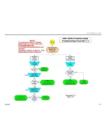
Страница 74: ...TVP 21 71 4 Protection Circuits Flowchart C 3 Figure 4 4 ...
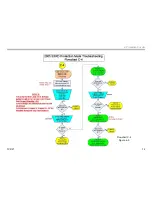
Страница 75: ...TVP 21 72 4 Protection Circuits Flowchart C 4 Figure 4 5 ...
Страница 87: ...TVP 21 84 5 Video Processing System No Video Flowchart D Figure 5 2 Troubleshooting Flowcharts ...
Страница 88: ...TVP 21 85 5 Video Processing System Video Distortion Flowchart E Figure 5 3 ...
Страница 89: ...TVP 21 86 5 Video Processing System Optical Block Flowchart F Figure 5 4 ...
Страница 98: ...TVP 21 95 6 Audio Processing System Troubleshooting Flowchart ...
Страница 102: ...TVP 21 99 Appendix 2005 SXRD Service Mode Options ...