


TVP-21
82
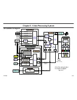
5. Video Processing System
•
Memory Stick
JPEG photograph and MPEG1 movie
are viewed using the Memory
Stick media device and this input. This input supports all Memory
Stick media up to and including the Memory Stick PRO 1GB. This
input does not support high-speed transfer and MagicGate copyright
protection features.
•
i-Link
The i-Link connection is Sony’s IEEE-1394 or Fire-Wire connection.
The i-Link connection transports digital video, audio, and control
information between any i-Link compatible device. The control
information can be used to control the external device (e.g. a
camcorder) from the TV remote control.
Typical external devices are the Camcorder, DVD, DVR, Satellite
Receivers, and A/V Receiver.
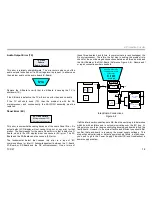
Video Circuits Functional Description
Reference Figure 5-1
You can divide the Video Processing system into the following four
separate sections.
•
Analog Video Switching Section
•
Digital Video Circuits Section
•
Video Processing Section
•
LCD Drive Circuits Section
The
ASU-Board
receives all
analog video inputs
(Video 1, 2, 3, 4, 5,
Sub-Tuner, and Main Tuner), which are then applied to, and switched by
IC303. The inputs are directed to either the Main or Sub analog output
on IC303 depending on the display configuration. Only Video Inputs 1,
2, and 3 can be displayed in the right-side Sub-picture panel in the twin
picture mode.
The Sub-Picture signal output (used for right-side panel picture for Twin
and Favorite display modes) is applied to the Sub Chroma-Decoder
IC4300 on the DSU-Board.
The Main-Picture signal output is applied to the Main Chroma-Decoder
IC7701 on the DSU-Board.
The
Digital Module Block (DMB)
is the interface for all
digital video
inputs
(ATSC Tuner, CableCard, Memory Stick, i-Link, and HDMI). The
ATI microprocessor controls the switching for all digital inputs except
for the HDMI, it also generates the User Menu and QM Service mode
graphics.
NOTE:
The Main NTSC Tuner is located in the DMB, however, the signal
is sent back to the ASU-Board to be switched by IC303 along with the
other analog signals.
The
ATSC tuner
receives all
digital CATV and Over-the Air signals
(Unscrambled & Scrambled)
, however, without a CableCard inserted
only the unscrambled (or In-the-Clear) signals will be displayed. To
display scrambled (or premium) digital channels a CableCard or Cable-
Box must be purchased form the local cable provider. In the case of a
CableCard
, the card is programmed for the particular channels paid for
by the customer. The Cablecard is inserted into the PCMCIA slot and the
cablecard control detects the received scramble channels and processes
those scrambled channels purchasd by the customer for display.
The outputs (Digital Video, Digital Graphics, and HDMI) of the DMB are
applied to the DSU-Board through two Low Voltage Differential Signal
(LVDS) cables.
The
DSU-Board
contains two CCP-X IC’s (Analog-to-Digital Conversion
ADC and Chroma Decoders), one for the main-picture (analog and digital)
processing and one for the sub-picture (analog only) processing. In the
case of the Main and Sub-picture analog signals the CCP-X IC’s perform
ADC, Chroma Decoding, Block Noise Reduction, and for the composite
480i signal 3D comb filtering. For the Main-picture digital signal the ADC
is bypassed since the signal is already in the digital format.
Содержание KDS-R60XBR1 - 60" Rear Projection TV
Страница 1: ...Models KDS R50XBR1 KDS R60XBR1 Diagnostics and Troubleshooting Course TVP 21 Training Manual ...
Страница 49: ...TVP 21 46 Disassembly Procedures Wire Routing Diagrams Wire Routing Diagrams ...
Страница 50: ...TVP 21 47 Disassembly Procedures Wire Routing Diagrams cont ...
Страница 51: ...TVP 21 48 Disassembly Procedures Wire Routing Diagrams cont ...
Страница 52: ...TVP 21 49 Disassembly Procedures Wire Routing Diagrams cont ...
Страница 53: ...TVP 21 50 Disassembly Procedures Wire Routing Diagrams cont ...
Страница 58: ...TVP 21 55 Chapter 2 Initial Contact Analysis ...
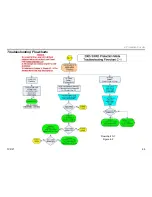
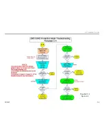
Страница 72: ...TVP 21 69 4 Protection Circuits Troubleshooting Flowcharts Flowchart C 1 Figure 4 2 ...
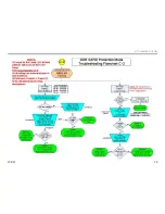
Страница 73: ...TVP 21 70 4 Protection Circuits Flowchart C 2 Figure 4 3 ...
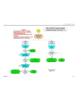
Страница 74: ...TVP 21 71 4 Protection Circuits Flowchart C 3 Figure 4 4 ...
Страница 75: ...TVP 21 72 4 Protection Circuits Flowchart C 4 Figure 4 5 ...
Страница 87: ...TVP 21 84 5 Video Processing System No Video Flowchart D Figure 5 2 Troubleshooting Flowcharts ...
Страница 88: ...TVP 21 85 5 Video Processing System Video Distortion Flowchart E Figure 5 3 ...
Страница 89: ...TVP 21 86 5 Video Processing System Optical Block Flowchart F Figure 5 4 ...
Страница 98: ...TVP 21 95 6 Audio Processing System Troubleshooting Flowchart ...
Страница 102: ...TVP 21 99 Appendix 2005 SXRD Service Mode Options ...