


TVP-21
87
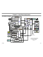
5. Video Processing System
Troubleshooting Flowchart Step Descriptions
When a video problem occurs you will experience one of the two following
symptoms.
•
No Video
•
Distorted Video
The main objective when troubleshooting one of the previously listed
symptoms is to determine if the defective exists in the Optical Block,
ASU/DSU Assembly, or Power Supply System. The three following
troubleshooting flowcharts have been designed to effectively and
efficiently locate the defective component using mostly visual indicators
and symptoms. The three flowcharts are as follows.
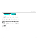
•
No Video Troubleshooting Flowchart D
•
Video Distortion Troubleshooting Flowchart E
•
Optical Block Troubleshooting Flowchart F
No Video
No Video
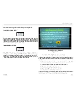
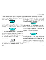
The first step when a “No Video” defect occurs is to determine if video is
missing on all video input sources, or if there is missing video only on one
or two video input sources.
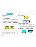
Is Video Missing
on
All Inputs
?
1,2,3 etc.
No
Yes
If the video is missing only on one or two inputs then you will go to the
“Video Distortion” troubleshooting flowchart E, which will be discussed in
the next flowchart description. However, if there is no video on all video
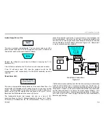
input sources the next question to ask is, is the Red LED flashing. In
other words, is the unit shutting down and going into protection mode.
Is
RED LED
Flashing?
No
Yes
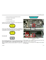
If the Red LED is flashing, this means that a protection circuit has detected
an error and the DE microprocessor is shutting the unit OFF and placing
it into a particular protection mode. In this case, you should go to one of
the Protection Mode troubleshooting flowcharts (C1, C2, or C3) found in
the Chapter 4. Observe the Red LED flash pattern (e.g. 2X) and proceed
to that particular flowchart.
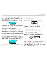
If the Red LED is not flashing the next step is to check if any OSD’s can
be displayed
Содержание KDS-R60XBR1 - 60" Rear Projection TV
Страница 1: ...Models KDS R50XBR1 KDS R60XBR1 Diagnostics and Troubleshooting Course TVP 21 Training Manual ...
Страница 49: ...TVP 21 46 Disassembly Procedures Wire Routing Diagrams Wire Routing Diagrams ...
Страница 50: ...TVP 21 47 Disassembly Procedures Wire Routing Diagrams cont ...
Страница 51: ...TVP 21 48 Disassembly Procedures Wire Routing Diagrams cont ...
Страница 52: ...TVP 21 49 Disassembly Procedures Wire Routing Diagrams cont ...
Страница 53: ...TVP 21 50 Disassembly Procedures Wire Routing Diagrams cont ...
Страница 58: ...TVP 21 55 Chapter 2 Initial Contact Analysis ...
Страница 72: ...TVP 21 69 4 Protection Circuits Troubleshooting Flowcharts Flowchart C 1 Figure 4 2 ...
Страница 73: ...TVP 21 70 4 Protection Circuits Flowchart C 2 Figure 4 3 ...
Страница 74: ...TVP 21 71 4 Protection Circuits Flowchart C 3 Figure 4 4 ...
Страница 75: ...TVP 21 72 4 Protection Circuits Flowchart C 4 Figure 4 5 ...
Страница 87: ...TVP 21 84 5 Video Processing System No Video Flowchart D Figure 5 2 Troubleshooting Flowcharts ...
Страница 88: ...TVP 21 85 5 Video Processing System Video Distortion Flowchart E Figure 5 3 ...
Страница 89: ...TVP 21 86 5 Video Processing System Optical Block Flowchart F Figure 5 4 ...
Страница 98: ...TVP 21 95 6 Audio Processing System Troubleshooting Flowchart ...
Страница 102: ...TVP 21 99 Appendix 2005 SXRD Service Mode Options ...