5-3(E)
FDDR-7000 IM
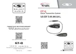
5-3. Installation of Operation Software
CN4
S3
S301
S302
ND300
ND301
D10
D11
D12
D13
D3
D4
D5
D6
D7
D8
D305
D300
CN300
D507
CN5
D2
D24
D1
D35
D36
D37
ND1
ND2
CNT1
CNT2
CNT3
CNT4
S2
D505
D508
D301
D302
D303
D304
ON
1 2 3 4 5 6 7 8
S3
*
(SW1), S301
*
(SW2)
Default setting by installation
5-3. Installation of Operation Software
m
1.
Data stored in HDD can be damaged when Install of Operation Software is performed.
Be sure to make a backup of the data to a VCR (Video Cassette Recorder) or other media before
performing the resource setup.
2.
If the FARAD system is operating, shut it down according to section “5-2-2. System Shut Down “
before starting to install the Operation Software.
3.
Remove the front panel of the FDDR-7000 (Multi-channel disk recorder) to gain access to the
switches (DIP) on CPU-253 to be set. Refer to section “1-5. Installation and Removal of Exterior
Parts.”
Procedure
1.
Set the switches (DIP) on the CPU-253 board as follows.
Set S3 (SW1)-1 to the ON position. Set all of the switches from S3 (SW1)-2 to S3 (SW1)-8 to the
OFF positions.
Set S301 (SW2)-1 to the ON position. Set all of the switches from S301 (SW2)-2 to S301 (SW2)-8
to the OFF positions.
*
( ) indicate switch name.
(Side-A/Component side)
2.
Turn on the POWER switch of the FDDR-7000.
n
The Operation Software can be installed provided the BKFD-7009/7009A (HDD unit) is not installed
in the FDDR-7000 and BKFD-7800 (HDD extension box), and when the main power of the BKFD-
7800 is turned off.
3.
Confirm the following display on the 7-segment LED (ND1, ND2, ND300 and ND301) on the CPU-
253 board.
“d0” appears on the 7-segment LED (ND1 and ND2).
The 7-segment LED looks as if its segments are cycling throughout the LED (ND300 and ND301).
n
If the 7-segment LED does not appear as described in step 3 even after one minute has passed, the
switches (DIP) are not set correctly. Turn off the main power of the FDDR-7000 and repeat the
above described procedure from step 1.