Sony CSP-5000E Скачать руководство пользователя страница 73

5-6

CSP-5000E

CSPK-5000E

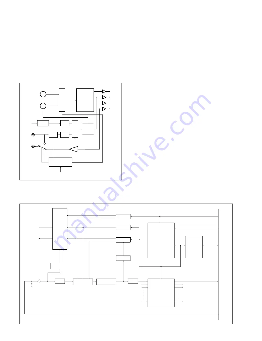
[Sync control block]

• The signal generator IC CXD1159Q (IC509) produces

composite sync signals.

• This block synchronizes the composite signals with

external signals. The block diagram of the sync signal

circuit is given below.

SYNC CONTROL BLOCK

Input Board (IPM-77)

Operation

• Installed in the CPS-5000E, the board provides the

following functions:

1

 To send multiple sync signals (VD-S),

2

 To send PTZ (panning, tilting, lens) control data,

3

 To compensate for cable losses

4

 To function as matrix switch

• The input video signals from CN13 are terminated by

R103 (75 

) and forwarded to add to the VD-S pulse

and the PTZ control data at the blanking periods. The

height of those pulse and data is adjusted in two steps by

the IC HC4052 (IC109), depending upon cable length.

• The video signals, combined with the VD-S pulse and

the PTZ control data, are sent through an emitter-

follower circuit to the IC ADG512 (IC108), where

IC108 restores the combined signals into the video

signals at an original signal level. The video signals are

then compensated for loss due to the cable and

forwarded to the sync separator and the clamp circuit

simultaneously.

• In the sync separator circuit, the VD, HD, and C. Sync

signals are extracted from the video signals and sent to

the PLD (IC32), where IC32 synchronizes them with the

PTZ control data.

• In the clamp circuit, the video signals are forwarded to

the IC MAX465 (IC76-IC79), where their output level is

adjusted to the specified level, and further sent to CN13.

PHASE

COMP.

IC506 TC8081AP

MUL

TIPLEXER.

MUL

TIPLEXER.

SYNC

SEP.

IC501 BA7046F

IC507 CX20158

PHASE

ADJ.

PHASE

ADJ.

SHAPING

CPU

IC113 MC68HC11M0

SG

IC509 CXD1159Q

OSC

VOC

FLD (VD/2)

VD

HD

C.SYNC

AC LINE

SYNC IN

SYNC OUT

14 MH

Z

IC512 SN74HC125

SW501

INT/LL

VD/PTZ CANCEL

MATRIX SW

X32

X8

AT-BUS

VD

MOTHER BOARD BUS

SW/PTZ-DATA

CLAMP

VIDEO

LOCAL BUS

PTZ-DATA CANCEL

PTZ-DATA

VD-S CANCEL

VD-S PULSE

VD-S PULSE

PTZ-DATA

VIDEO+VD+PTZ

VIDEO

VOLTAGE

REFERENCE

VD/PTZ

CABLE COMP

SYNC CHIP LEVEL

SYNC SEP

PLD

CLAMP

VD ON/OFF

VD-S PULSE

+

DRAM

CPU

INPUT BOARD (IPM-77)

Содержание CSP-5000E

Страница 1: ...SYSTEM CONTROLLER CSP 5000E SERVICE MANUAL INPUT BOARD CSPB 510VC OUTPUT BOARD CSPB 520VC SYSTEM KEYBOARD CSPK 5000E Vol 1 1st Edition ...

Страница 2: ...es acquéreurs de l équipement décrit dans ce manuel Sony Corporation interdit formellement la copie de quel que partie que ce soit de ce manuel ou son emploi pour tout autre but que des opérations ou entretiens de l équipement à moins d une permission écrite de Sony Corporation Das in dieser Anleitung enthaltene Material besteht aus informationen die Eigentum der Sony Corporation sind und ausschli...

Страница 3: ...sh and Italian for CE CSPB 520VC Part No 3 860 963 11 English French German Spanish and Italian for CE Describe how to operate this equipment Service Manual Vol 2 Not supplied with equipment Part No 9 977 305 21 Describes the board layouts schematic diagrams semiconductor pin assingments and parts lists Purpose of this manual Related Manuals MANUAL STRUCTURE The sections covered in the manual are ...

Страница 4: ......

Страница 5: ...nt of Chip Parts 2 10 2 5 INITIAL SETTINGS OF SWITCHES 2 11 2 5 1 CSP 5000E 2 11 2 5 2 CSPK 5000E 2 11 2 5 3 CSPB 510VC 2 11 2 5 4 CSPB 520VC 2 11 2 6 TOOL 2 12 3 TROUBULESHOOTING 4 ELECTRICAL ALIGNMENT 4 1 TEST EQUIPMENT AND TOOLS 4 1 4 2 CT 156 BOARD CSP 5000E ALIGNMENT 4 1 4 3 OPM 11 BOARD CSP 5000E CSPB 520VC ALIGNMENT 4 2 4 4 SY 211 BOARD CSPK 5000E ALIGNMENT 4 4 5 CIRCUIT DESCRIPTION AND BLO...

Страница 6: ......

Страница 7: ...n is extracted from operation manual 1 1 CSP 5000E SYSTEM CONTROLLER Operating Instructions 2 EN Before operating the unit please read this manual thoroughly and retain it for future reference 3 860 960 11 1 System Controller CSP 5000E 1997 by Sony Corporation ...

Страница 8: ... BTH601 H101 Raadpleeg uw leverancier over de verwijdering van de batterij op het moment dat u het apparaat bij einde levensduur afdankt Gooi de batterij niet weg maar lever hem in als KCA Bij dit produkt zijn batterijen geleverd Wanneer deze leeg zijn moet u ze niet weggooien maar inleveren als KCA 2 EN Features 4 EN Precautions 5 EN Location and Function of Parts and Controls 6 EN Connections 8 ...

Страница 9: ...sh and Italian System partitioning password protection The CSP 5000E accepts up to seven system keyboards enabling local and remote control by multiple operators Furthermore you can specify which of the cameras monitors and setup menu items are available to each operator Well chosen system partitions can limit the scenes available to each operator contributing to more efficient surveillance and en...

Страница 10: ...ignal when an alarm is activated This connector can be connected to an external device such as a time lapse VTR to activate it by an alarm signal 6 KBD I F keyboard interface connectors 1 to 7 Connects to the KBD I F connector of the CSPK 5000E System Keyboard not supplied 7 RCV I F receiver interface connector Connects to the RS 485 422A connector of the receiver not supplied or to the KBD I F co...

Страница 11: ... EN Do not use the line lock reference signal as a synchronization signal for the VD S lock cameras if such cameras are used 8 EN Preparation Inserting the Lithium Batteries Insert two CR2032 lithium batteries supplied into the system controller 1 Open the front panel and locate the battery holders 2 Insert the lithium batteries into the battery holders with correct polarity positive side facing u...

Страница 12: ... on the output boards Jumper pin Slot 1 Slot 2 Slot 3 Slot 4 CN105 VB1 VB9 VB17 VB25 CN106 VB2 VB10 VB18 VB26 CN107 VB3 VB11 VB19 VB27 CN108 VB4 VB12 VB20 VB28 CN109 VB5 VB13 VB21 VB29 CN110 VB6 VB14 VB22 VB30 CN111 VB7 VB15 VB23 VB31 CN112 VB8 VB16 VB24 VB32 Output board Jumper pins 10 EN Video input output numbers The video input and output numbers of the terminals on the input output boards are...

Страница 13: ...N Technical Information Reference Signal The following diagram shows the reference signal block When VS singal is input from the SYNC IN terminal The signal input from the SYNC IN terminal is output to the SYNC OUT terminal SYNC IN SYNC OUT 75 Ω Switches automatically Sync signal detection SW501 INT LL 75 Ω 75 Ω SW501 When no signal is input from the SYNC IN terminal The internal reference signal ...

Страница 14: ...IN 13 22 46 ALARM IN 28 ALARM IN 12 21 45 ALARM IN 27 ALARM IN 11 20 44 ALARM IN 26 ALARM IN 10 19 43 ALARM IN 25 ALARM IN 9 18 42 ALARM IN 24 ALARM IN 8 17 41 ALARM IN 23 ALARM IN 7 16 40 ALARM IN 22 ALARM IN 6 15 39 ALARM IN 21 ALARM IN 5 14 38 ALARM IN 20 ALARM IN 4 13 37 ALARM IN 19 ALARM IN 3 12 36 ALARM IN 18 ALARM IN 2 11 35 ALARM IN 17 ALARM IN 1 10 34 26 GND GND 9 1 Alarm input numbers Th...

Страница 15: ... PAL CCIR standard Inputs VIDEO INPUT connectors BNC 128 1Vp p 75 ohms composite video Outputs VIDEO OUTPUT connectors BNC 32 1Vp p 75 ohms composite video Reference input output SYNC IN connector BNC 1Vp p 75 ohms composite video SYNC OUT connector BNC 0 3Vp p 75 ohms composite sync Keyboard interface KBD I F connector RJ 45 8 pin RS 422A 7 RCV I F connector RJ 45 8 pin RS 422A 485 No 8 only Exte...

Страница 16: ... 1 2 CSPB 510VC INPUT BOARD Operating Instructions Page 2 Before operating the unit please read this manual thoroughly and retain it for future reference 3 860 962 11 1 Input Board CSPB 510VC 1997 by Sony Corporation ...

Страница 17: ...f the system controller is turned on Stopper Stopper Inserting the Input Boards 1 Open the front panel 2 Insert the input boards into one of the 16 slots slot 1 to 16 of the right side 3 Secure the board using the stopper 4 Close the front panel Video Input numbers The video input numbers of the terminals on the input boards are determined by the slot you inserted the boards Slot number Video inpu...

Страница 18: ...1 3 CSPB 520VC OUTPUT BOARD Operating Instructions Page 2 Before operating the unit please read this manual thoroughly and retain it for future reference 3 860 963 11 1 Output Board CSPB 520VC 1997 by Sony Corporation ...

Страница 19: ...t 2 Slot 3 Slot 4 CN105 VB1 VB9 VB17 VB25 CN106 VB2 VB10 VB18 VB26 CN107 VB3 VB11 VB19 VB27 CN108 VB4 VB12 VB20 VB28 CN109 VB5 VB13 VB21 VB29 CN110 VB6 VB14 VB22 VB30 CN111 VB7 VB15 VB23 VB31 CN112 VB8 VB16 VB24 VB32 Output board Jumper pins 2 Video Output Numbers The video output numbers of the terminals on the output boards are determined by the slot you inserted the boards Video output number 1...

Страница 20: ...4 CSPK 5000E SYSTEM KEYBOARD Operating Instructions 2 EN Before operating the unit please read this manual thoroughly and retain it for future reference System Keyboard 3 860 961 11 1 CSPK 5000E 1997 by Sony Corporation ...

Страница 21: ... About Sequence Tour and Event 19 EN Programming Sequences and Tours 22 EN Copying a Tour 24 EN Grouping Sequences 25 EN Programming an Event 26 EN Programming a Weekly Schedule 27 EN Programming a Daily Schedule 28 EN Configuring the System 29 EN Configuring the Input Source 29 EN Assigning IDs to cameras 29 EN Specifying a camera s cable length 30 EN Specifying the receiver type 31 EN Setting th...

Страница 22: ...tributing to more efficient surveillance and enhanced system security 4 EN On safety Operate on 220 to 240V AC Do not drop or place heavy objects on the power cord If the power cord is damaged turn off the power immediately Using the unit with a damaged power cord will result in hazard Disconnect the power cord from the AC outlet by pulling on the plug Never pull the cord itself If you spill liqui...

Страница 23: ... 8 RECALL key 9 10 key pad 0 CAMERA key PATTERN key MONITOR key TOUR key Joyball PAN TILTER keys º PRINT key ª WIPER key CAMERA POWER key AUX1 AUX2 AUX3 keys Function keys 6 EN 8 RECALL key page 12 EN Press this key to restart the sequence program once suspended 9 10 key pad Use it to enter a number 0 CAMERA key page 11 EN Press this key to switch to a specified camera PATTERN key page 41 EN Press...

Страница 24: ... VIDEO IN jack BNC type Connect to one of the VIDEO OUT connectors of the CSP 5000E System Controller 7 AC IN socket Connect to an AC power source with the AC power cord Location and Function of Parts and Controls 7 AC IN socket 6 VIDEO IN jack 5 CABLE COMP switch 4 VIDEO OUT jack 3 KBD I F connector 2 PRINTER connector 1 RESET switch AC IN VIDEO IN LNS CABLE COMP VIDEO OUT KBD I F PRINTER RESET 8...

Страница 25: ...em Controller is running low When this occurs you need to replace the battery Adjusting the contrast of the LCD screen While pressing down the SET key press the cursor keys to adjust the contrast of the LCD screen When the power is turned off and turned on again the contrast returns to the default value POWER switch SET key 10 key pad 10 EN Manually Switching Cameras and Monitors Selecting a camer...

Страница 26: ... on the monitor will be the master sequence 12 EN Manually Starting a Tour Program When particular needs arise you can also temporarily interrupt the routine surveillance program and manually select a tour program to run as described in the following steps See What is a tour on page 20 EN for explanation of a tour Example Run tour program 3 1 Enter the number 3 with the 10 key pad MONITOR X CAMERA...

Страница 27: ...he camera To control the lens Press the ZOOM WIDE TELE FOCUS NEAR FAR or IRIS CLOSE OPEN keys To control the camera s power Press the CAMERA POWER key Pressing the key again turns off the power To control the window wiper Press the WIPER key To control the auxiliary devices Press the AUX1 AUX2 or AUX3 key as desired 14 EN Using the Alarm Function Controlling Character Display on the Monitor First ...

Страница 28: ...oller s KBD I F connector number and the VIDEO OUT terminal number to which the System Keyborad is connected LANGUAGE Six languages are available for you to choose Japanese English French German Spanish and Italian Once chosen the language will be available for you to use to name cameras in the SOURCE ID menu SWITCHING PROGRAM menu This menu allows you to program surveillance It contains the follo...

Страница 29: ...N LOGOFF 17 EN Menu Tree Diagram Refer to the indicated pages for detailed explanations 18 EN Programming About Sequence Tour and Event The CSP 5000E System Controller allows for very flexible control of specific cameras and monitors for surveillance This is possible through programming sequences tours and events What is a sequence A sequence specifies all steps of camera switching on a monitor In...

Страница 30: ...AM 10 CAM 10 Preset 1 Preset 2 Monitor 1 Monitor 2 Monitor 3 Monitor 4 Tour 3 Tour 2 Tour 1 Tour 8 20 EN What is an event An event allows you to switch tours automatically according to time In the illustration above for example tour 3 is invoked during the night time and tour 1 in the morning In other words event is a schedule for switching tours for a 24 hour Up to 8 steps in switching tours can ...

Страница 31: ...32 5 Select a monitor number MONITOR1 in this example to start creating a sequence for that monitor and then press the SET key TOUR1 MONITOR1 STEP CAM PRE DWL 1 1 0 2 1 0 3 1 0 4 1 0 5 1 0 6 1 0 7 1 0 8 1 0 INTERNAL 22 EN 6 Start with step 1 Use the cursor keys to move around then with the 10 key pad enter a camera number its preset position and dwell time The preset position must have been set in...

Страница 32: ...our In a group the sequence with the smallest monitor number becomes the master sequence for comparison Grouping will take effect only when one of the following conditions is met Dwell times in the master sequence are all identical The number of steps for all other monitors in the group is equal to that of the master sequence The number of steps for all other monitors in the group is multiple of t...

Страница 33: ... 6 When you are ready press the SET key to accept the changes You can create up to 8 events of the day then you need to specify when to activate the event See the following sections on planning a schedule 26 EN Programming a Weekly Schedule After you have created the events of tours for a day you need to tie them to a schedule so that when the day and time come the event will activate to start the...

Страница 34: ...AY key the names will appear on the selected monitor 1 From the main menu select INPUT CONFIGURE and then press the SET key INPUT CONFIGURE SOURCE ID CABLE COMPENSATION RECEIVER TYPE VD P T LIMIT 2 Select SOURCE ID and then press the SET key SOURCE ID ABC CAM ID 1 2 3 4 5 6 7 8 3 Select a camera number If necessary press the NEXT or PREVIOUS key to see other pages If the keyboard monitor is config...

Страница 35: ...e 0 160 400 700 900 Length 160m 400m 700m 900m 1200m cable type 5C 2V 30 EN Specifying the receiver type Use the RECEIVER TYPE setting to specify the type of camera in use 1 From the main menu select INPUT CONFIGURE and then press the SET key INPUT CONFIGURE SOURCE ID CABLE COMPENSATION RECEIVER TYPE VD P T LIMIT 2 Select RECEIVER TYPE and then press the SET key RECEIVER TYPE CAM TYPE 1 NONE 2 NON...

Страница 36: ...n horizontal and vertical directions This is available only when the receiver type of the camera is TWIST PAIR 1 From the main menu select INPUT COFIGURE and then press the SET key INPUT CONFIGURE SOURCE ID CABLE COMPENSATION RECEIVER TYPE VD P T LIMIT 2 Select P T LIMIT and then press the SET key P T LIMIT SELECT RECEIVER NO 1 9 17 25 2 10 18 26 3 11 19 27 4 12 20 28 5 13 21 29 6 14 22 30 7 15 23...

Страница 37: ... SYSTEM CONFIGURE DATE TIME KEYBOARD MONITOR LANGUAGE 2 Select KEYBOARD MONITOR and then press the SET key KEYBOARD MONITOR I F MONITOR 1 1 2 2 3 3 4 4 5 5 6 6 7 7 8 TWIST PAIR 3 Use the cursor keys to select a KBD I F number then enter the corresponding VIDEO OUT terminal number For example if a keyboard is connected to the KBD I F connector 1 and the VIDEO OUT terminal 32 select I F 1 and enter ...

Страница 38: ...R and then press the SET key ALARM PROGRAM CONTROLLER SELECT ALARM IN NO 1 9 17 25 2 10 18 26 3 11 19 27 4 12 20 28 5 13 21 29 6 14 22 30 7 15 23 31 8 16 24 32 36 EN 4 Select an alarm 1 in this example then press the SET key If necessary press the NEXT or PREVIOUS key to see other pages PROGRAM CONTROLLER ALARM IN 1 OUT TIME MON CAM PRE 5 At the OUT field enter the number of alarm output terminal ...

Страница 39: ...3 58 05 33 2 13 11 96 13 59 10 128 4 15 11 96 17 03 30 5 16 11 96 08 27 15 256 18 11 96 21 18 42 3 The most recent alarms appear on the screen If necessary press the NEXT or PREVIOUS key to see other pages 4 When you are ready press the MENU key to exit 38 EN Defining the Preset Position and Pan Tilt Pattern Depending on the receiver used you can define preset positions and pan tilt patterns for a...

Страница 40: ...for this camera that you want to clear you can repeat this step to clear them 6 When you are ready press the MENU key 40 EN Defining the pan tilt pattern You can define the pan tilt pattern up to 30 seconds for the currently selected camera The defined pan tilt pattern can be recalled by the PATTERN key Note that this function can be used only with specific pan tilt units 1 Select a camera you wan...

Страница 41: ...Y MENU CAMERA MONITOR TOUR 2 Select PTZ PRIORITY and then press the SET key PASSWORD PARTITION PTZ PRIORITY 8 3 Enter a number 1 being the highest and 8 the lowest priority 4 When you are ready press the SET key to accept the change If the same priority is assigned to the different keyboards the keyboard which issued a command first is given a higher priority 42 EN Limiting access to the system me...

Страница 42: ... From the PASSWORD menu select a user and then press the SET key PASSWORD PARTITION PTZ PRIORITY MENU CAMERA MONITOR TOUR 2 Select TOUR and then press the SET key PASSWORD PARTITION TOUR 1 ON 2 ON 3 ON 4 ON 5 ON 6 ON 7 ON 8 ON 3 Select a tour 4 Use the cursor keys to turn ON or OFF the tour When off the tour will not be available to the user 5 Repeat the same procedure with other tours When you ar...

Страница 43: ...witching Regulator TDKFAW05 30R DC Fan Motor DC Fan Motor 1 LED 22 Board Power Indicator 2 CSPB 520VC OPM 11Board Output Board 3 MB 596 Board Mother Board 4 CN 1111 Board Connector Board PC block AT 5 CN 1093 Board Connector Board KBD I F 6 CN 1110 Board Connector Board alarm OUT 7 CN 1109B Board Connector Board alarm IN 8 CN 1109A Board Connector Board alarm IN 9 CN 1092 Board Connector Board vid...

Страница 44: ...2 2 CSP 5000E CSPK 5000E 2 1 2 CSPK 5000E 1 2 3 1 KIO 9 Board Keyboard Assembly Key Board 2 IF 511 Board Connector Board 3 SY 211 Board System Control ...

Страница 45: ...rews PSW3x6 and remove the front panel Cabinet 1 Unscrew the eight screws PSW4x10 and remove the Rack Angle Assembly 2 Unscrew the four BW screws b and pull out the main chassis in direction B Note Hook the bottom edge of the main chassis into the two claws on the cabinet and install the main chassis B A Screw a BW Screw a BW Screw b BW Screw a BW Top Panel Screw PSW4x10 Screw PSW4x10 Screw PSW4x1...

Страница 46: ...807 808 CN802 806 CN810 812 Handle Handle Connector Panel 1 Unscrew the four screws PSW4x8 and pull the handle in the arrow direction and remove the connector panel 2 Disconnect the ten connectors CN121 to 130 on the MB 596 board 3 Disconnect the ten connectors CN802 to 806 808 to 812 on the CN 1094 Board ...

Страница 47: ...move the joy ball Joyball 2 Unscrew the five screws B3x6 3 Disconnect the one connector CN104 on the SY 211 board 4 Unscrew the two screws PS3x6 and remove the switch bracket in the upper cover Screw B3x6 Screw B3x6 Screw PS3x6 Switch Bracket Upper Cover CN104 ...

Страница 48: ...our screws BVTT3x8 and remove the power supply in the arrow direction 2 3 2 DC Fan Motor Front Side Binding Band Binding Band CN613 CPU 185 Board Screw B4x30 DC Fan Motor Label 1 Open the front panel and disconnect one connector CN613 on the CPU 185 Board Refer to section 2 2 Removal of Cabinet 2 Cut the binding band which hold the harness with a nipper 3 Unscrew the four screws B4x30 on each DC f...

Страница 49: ...ain chassis in the direction of the arrow 4 Disconnect the two connectors CN135 136 on the MB 596 Board unscrew the four screws B4x30 on each DC fan motor and remove the DC fan motors and bracket Note Install the DC fan motor as shown in the figure noting the direction of the motor labels 2 3 4 MB 596 Board 1 Remove the top panel and rear panel Refer to section 2 2 Removal of Cabinet 2 Open the fr...

Страница 50: ... the main chassis in direction A 6 Unscrew the three screws a BVTT3x8 7 Unscrew the four screws PSW3x6 and then remove the MB reinforcement A and B 8 Pull out the MB 596 Board in direction B B B MB 596 Board A Screw b PSW3x6 Screw b PSW3x6 Screw a BVTT3x8 MB Reinforcement A MB Reinforcement B Main Chassis ...

Страница 51: ...n is firm and lock the levers of the CPU 185 board A A CN607 CN606 CPU 185 Board 2 3 6 Plug in Board Extraction and Insertion Eject Lever EXTRACTION INSERTION Plug in board Extraction Pull up the eject levers on the plug in board in the arrow direction pull out the boards from the MB 596 board connectors Plug in Board Insertion Insert the plug in board by pushing its eject levers forward as shown ...

Страница 52: ... per pin Replacement of Resistor and Capacitor 1 Place the soldering iron tip onto the chip part and heat it up until the solder is melted When the solder is melted slide the chip part aside 2 Make sure that there is no pattern peeling damage and or bridge around the desoldering position 3 After removing the chip part presolder the area in which the new chip part is to be placed with a thin layer ...

Страница 53: ...SPK 5000E SY 211 Board A side 2 5 3 CSPB 510VC IPM 77 Board A side 2 5 4 CSPB 520VC OPM 11 Board A side ON S602 4 3 2 1 ON LL INT S101 SW501 4 3 2 1 S103 SW REG S101 200 PIN CONNECTOR ON ON NTSC PAL S11 S12 1 2 3 4 4 3 2 1 200 PIN CONNECTOR ON ON S104 S101 1 2 3 8 7 6 5 4 3 2 1 ON S102 8 7 6 5 NTSC NORMAL 4 3 2 TEST PAL 1 4 ...

Страница 54: ...31 350 A This is used to inspect and adjust the IPM 77 and OPM 11 boards Extension Board EXP 156 Sony part No J 6431 360 A This is used to inspect and adjust the CT 156 board Extension Board EXP 185 Sony part No J 6431 370 A This is used to inspect and adjust the CPU 185 board ...

Страница 55: ... simply because of wrong settings FLOWCHART Trouble No AC mains Uncontrollable from keyboard No picture from camera Camera uncontrollable No panning no tilting No control over lens No control over power switch Camera picture out of sync Others No alarm No cable compensation No data backup Peripherals out of order Go to CHARTS 1 and 2 Go to CHART 3 Go to CHARTS 4 5 and 6 Go to CHART 7 Go to CHART 8...

Страница 56: ...Remove CN133 and 134 from the MB 596 board Verify that the LED on the switching regulator lights 1 The power supply load may be short circuited Check the load Plug in the power supply cord correctly Verify that the LED on the front panel lights Feed the AC mains as specified Verify that the LED on the front panel lights Verify that harness and connectors are in good shape The switching regulator i...

Страница 57: ...e DC 5V at TP101 on the SY 211 board Verify that the voltage is DC 5V The SY 211 board is defective Plug in the power supply cord correctly Verify that the LED lights Feed the AC mains as specified Verify that the LED lights Replace the fuse after solving the problems Check to see if the power supply secondary is short circuited The switching regulator is out of order Replace it End NO YES YES NO ...

Страница 58: ...controller Verify that the WELCOME display disappears End Exchange the KBD I F connector of the system controller Verify that the WELCOME display disappears The KBD I F connector of the system controller is partly defective Observe TXD of the KBD I F connector of the system controller Verify that the pulse is observed The KBD I F connector of the system controller is defective Observe TXD of the K...

Страница 59: ...NO NO NO NO NO NO Verify that the LED on the switching regulator lights Verify that the output voltage is as specified Refer to the manuals for peripherals in question Remove CN133 and 134 from the MB 596 board Verify that the LED on the switching regulator lights Verify that the output voltage is as specified The power supply section on a certain board is out of order Verify that the boards are i...

Страница 60: ...ailable The camera monitor and or cable are defective The input channel is defective Refer to the manuals for peripherals in question Exchange the input board Verify that picture is available The input board is defective Switch the output channel The input board is out of order Repair it Select the camera and the monitor Verify that picture is available Exchange the output board Verify that pictur...

Страница 61: ... the monitor The camera monitor and or cable are defective Press the menu key for 2 sec or longer Refer to the manuals for peripherals in question Repair the video input section Verify that harness and connectors are in good shape Verify that the Menu display is available Video output sections after the character generator are defective Repair the video output section Verify that harness and conne...

Страница 62: ...and panning tilting sections are defective Refer to the manuals for peripherals in question Exchange the input board Verify that control data are observed on 18H and 19H when trying to control The input board is defective The input board is out of order Repair it Exchange the CPU 185 board Verify that control data are observed on 18H and 19H when trying to control The CPU 185 board is defective Th...

Страница 63: ...wing before going to CHART 8 Select the camera in question using the keyboard Set the VD Equipment Waveform monitor YES YES YES NO NO NO Camera picture out of sync VD sync Connect the waveform monitor to the video input section Verify that VD pulses are observed The camera is defective Refer to the manuals for the camera Exchange the input board Verify that VD pulses are observed The input board i...

Страница 64: ...rd EXP 156 PLL Adjustment of Sync signals 1 Feed color bar signals into EXT SYNC IN 2 Connect a digital voltmeter to TP503 PLL Phase Adjustment of Sync signals INT 1 Feed color bar signals into EXT SYNC IN 2 Connect an oscilloscope as follows CH1 TP501 VS CH2 TP504 C SYNC DC1 9V 0 1V Adjust the phase as shown 1 CT501 1 RV502 Phase Adjustment of Sync signals LL 1 Operate the CSP 5000E on AC 50Hz ma...

Страница 65: ...s into the video camera IN and select it using the keyboard 2 Connect a monitor TV to ch 1 3 Connect an oscilloscope as follows CH1 TP101 CH2 TP122 4 Similarly repeat the adjustments for ch 2 through ch 8 The appropriate test points and variable resistors are shown in the following chart 5 Repeat the adjustments for the other channel groups slots if required VB changes as shown in the following ch...

Страница 66: ... TP154 TP164 TP176 TP186 TP196 RV RV101 RV104 RV107 RV110 RV113 RV116 RV119 RV122 CV CV101 CV103 CV105 CV107 CV109 CV111 CV113 CV115 Jumper Pins CN105 CN106 CN107 CN108 CN109 CN110 CN111 CN112 ch1 8 VB1 VB2 VB3 VB4 VB5 VB6 VB7 VB8 Slot 1 ch9 16 VB9 VB10 VB11 VB12 VB13 VB14 VB15 VB16 Slot 2 ch17 24 VB17 VB18 VB19 VB20 VB21 VB22 VB23 VB24 Slot 3 ch25 32 VB25 VB26 VB27 VB28 VB29 VB30 VB31 VB32 Slot 4...

Страница 67: ...ter Generator 1 Feed color bar signals into the video camera IN and select it using the keyboard 2 Press the menu key for 2 sec or longer to display the menu on the monitor 3 Connect an oscilloscope as follows CH1 TP123 CH2 TP124 Adjust the phase as shown 1 RV101 2 8 µsec Size Adjustment of Character Generator 1 Feed color bar signals into the video camera IN and select it using the keyboard 2 Pre...

Страница 68: ...IN SYNC ALARM KBD I F 8 1 VIDEO OUT 8 1 HC11 CG HC11 CG OPM 11 HC11 CG 32 4 55 3 3 3 1 4 3 2 16 15 6 5 4 3 2 1 DATA BUS VIDEO SYNC AT SWCNTL IDCNTL KBDATA HC11 CG SW ALARM AT KBDIF CT 156 CPU 185 OUTPUT MODULE OPM 11 OUTPUT MODULE OUTPUT MODULE OPM 11 OUTPUT MODULE OPM 11 INPUT MODULE IPM 77 IPM 77 INPUT MODULE IPM 77 INPUT MODULE IPM 77 INPUT MODULE INPUT MODULE IPM 77 IPM 77 INPUT MODULE IPM 77 ...

Страница 69: ...it produces line lock signals Signal Input Output Boards The boards are connector boards for various signals The signals are VIDEO IN OUT ALARM IN OUT EXT TIMING IN KBD I F SYNC IN OUT RS 232C PRINTER VGA KBD MOUSE and so on MAIN CONTROL BOARD CPU 185 MA728 X2 A D RXD1 8 IC631 IC626 IC633 RESET S601 RESET S 80745AM IC606 SD BUS SN74HC14ANS BUFFER IC644 KB BUS IC639 MC74HC138 X3 IC634 IC638 IC616 I...

Страница 70: ...its data to the PC block AT which in turn sends the CSPK 5000E s LCD commands to indicate a warning when the battery power becomes less than specified The lithium battery holds the setting memory for the card PC and the SRAM IC639 in which the CSP 5000E s partial operation is set Circuit Description Main Control Board CPU 185 Outline The CPU 185 board mainly acts as the central control section for...

Страница 71: ... Block KBIF receives data from PC block AT through the Dual Port RAM IC618 it transfers them to the keyboard answers them back to PC block AT or processes them within Keyboard IF Block KBIF depending on the data received The data communication control IC IC617 IC623 IC629 IC635 of Keyboard IF Block KBIF sends priority signals to the keyboard each time data of 1 byte are processed similarly to the ...

Страница 72: ... HC11 BUS I O DECODE RAM ROM MULTIPLEXER I O DECODE SPI 2 SPI 1 Alarm control block This block controls the following 1 Data exchange with the keyboard by the dual port RAM MB8421 IC101 This block receives the data for the alarm and switch controls from the keyboard and stores them in memory as program data The data are then if required sent back to the keyboard 2 Reading of alarm input signals th...

Страница 73: ...here IC108 restores the combined signals into the video signals at an original signal level The video signals are then compensated for loss due to the cable and forwarded to the sync separator and the clamp circuit simultaneously In the sync separator circuit the VD HD and C Sync signals are extracted from the video signals and sent to the PLD IC32 where IC32 synchronizes them with the PTZ control...

Страница 74: ...which eight signals are chosen by CN105 through CN112 out of 32 signals available from the mother board OUTPUT BOARD OPM 11 2 Digital signal circuit Micro computer MC68HC11M0CFU4 IC113 provides the following functions 1 Command reception by the dual port RAM MB8421 IC194 To turn on or off character generator display according to commands received 2 Data reception for controlling the character gene...

Страница 75: ...nal circuit The DC component of video signals from CN102 are removed by C103 and forwarded to the subsequent cable compensation circuit where IC105 s gain and frequency characteristics are adjusted in three steps S M L by the switching signals sent from CN103 and set according to coaxial cables type length being in use After the cable compensation circuit the video signals go to the character gene...

Страница 76: ...rom CN301 The data of the depressed key are led to the Port A The switches SW301 SW349 form a matrix circuit and according to the data given from the Port A and Port B the circuit determines which switch is depressed LED drive circuit The buffer IC IC302 drives LED s With the Port set in LOW mode the LED illuminates The Port setting of the 8255A IC301 is as follows PA0 PA7 Key scan input PB0 PB5 K...

Страница 77: ......

Страница 78: ...Sony Corporation Image Sound Communication Company CSP 5000E CE CSPB 510VC CE CSPB 520VC CE CSPK 5000E CE 9 977 305 11 Printed in Japan 1997 9 04 1997 Published by Engineering Services Dept ...

Отзывы: