4-31
CCU-TX7 (E)/V1
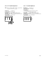
4-7-11. CAM TONE Adjustment
Notes :
• This adjustment for the following cameras must be
completed before this adjustment.
[For NTSC] DXC-637 or DXC-D30
[For PAL]
DXC-637P or DXC-30P
Equipment
:
Oscilloscope (DC mode)
To be extended
:
AA-90 board
Test point
:
TP7 (GND : E2)/AA-90 board
Adjustment point :
1
RV101 (TONE TUNE)/
AA-90 board
Adjustment Procedures :
1.
1
RV101 (TONE TUNE)/AA-90 board
→
"Mechanical center"
2. Turn
1
RV101 (TONE TUNE)/AA-90 board slowly
clockwise and stop it at the point where the sine wave
signal just appears.
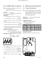
Measure the DC voltage "a"
⋅⋅⋅
Fig-1
3. Turn
1
RV101 (TONE TUNE)/AA-90 board slowly
counterclockwise and stop it at the point where the sine
wave signal just appears.
Measure the DC voltage "b"
⋅⋅⋅
Fig-2
4. Adjust the DC level with
1
RV101 (TONE TUNE)/AA-
90 board so that "a" is equal to "b"
⋅⋅⋅
Fig-3
(fig. 2)
Equal (a)
Equal (b)
Turn slowly counterclockwise
(fig. 3)
Equal (a)
Equal (b)
A
B
RV101 (A = B)
(fig. 1)
Equal (a)
Turn slowly clockwise
Mechanical center
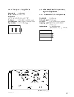
4-7-10. CAM DATA Demodulation Adjustment
Notes :
• This adjustment for the following cameras must be
completed before this adjustment.
[For NTSC] DXC-637 or DXC-D30
[For PAL]
DXC-637P or DXC-30P
• Perform the adjustment only when replacing
1
LV101 (5.6
MHz TUNE)/AA-90 board.
Equipment
:
Oscilloscope
20 MHz BW Limit : ON
INPUT made
: DC
To be extended
:
AA-90 board
Test point
TP6 (GND : E2)/AA-90 board
Adjustment point :
1
LV101 (5.6 MHz TUNE)/
AA-90 board
Specifications
:
_
100
±
40 mV dc
A
GND
(
)


