4-26
CCU-TX7 (E)/V1
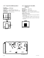
4-7. TRIAX Interface System Adjustment
4-7-1. Frequency Set Adjustment
Note :
Check to see that no signal is input to the INCOM
connector and PGM connector on the CCU-TX7/
TX7P rear panel or the CCU-TX7/TX7P front panel.
Perform the adjustment only when replacing the
following part on AA-90 board.
LV1, 21, 41, 81, D2, 22, 42, 62
Equipment
:
Frequency counter, Digital voltmeter
To be extended :
AA-90 board
Adjustment Procedures :
1. Remove the ES-20 and CT-181 boards.
2. Turn on the power switch "ON".
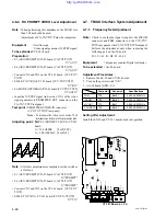
3. AA-90 board (GND : E1)
Test point
Adj. point
Specifications
PGM
TP5
1
LV81
4.300
±
0.005 MHz
INCOM
TP3
1
LV41
3.600
±
0.005 MHz
H CONT
TP1
1
LV1
3.000
±
0.005 MHz
CCU DATA
TP2
1
LV21
2.500
±
0.005 MHz
Setting after Adjustment :
Install the ES-20 and CT-181 boards back into position.
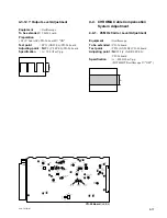
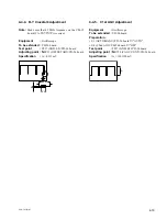
4-6-4. RX PROMPT VIDEO Level Adjustment
Note :
When performing this adjustment, the TRIAX less
than 300 m should be used.
Adjustment of CA-TX7/TX7P must be completed.
Equipment
:
Oscilloscope,
Video signal generator (10 STEP signal)
To be extended :
CT-181 board
Preparation :
• S1 (AUX/PROMPT)/YD-25 board (CA-TX7/TX7P)
→
"AUX"
• S6 (AUX/PROMPT)/YD-25 board (CA-TX7/TX7P)
→
"AUX"
• Connect CN8 and CN3 on the CT-181 board. (CCU-TX7/
TX7P)
• S2002 (TX
↔
RX)/CT-181 board (CCU-TX7/TX7P)
→
"RX"
• S1 (MODE AUTO/MAN)/YD-26 board (CCU TX7/TX7P)
→
"AUTO"
• Input the 10 STEP signal (sub-carrier : ON) of the video
signal generator to PROMPTER OUT connector on the
CA-TX7/TX7P real panel.
Test point :
PROMPTER VIDEO IN connector
(CCU-TX7/TX7P rear panel)
Note : To measure the video level, make 75
Z
termination on the waveform monitor side.
Adjusting point
:
1
RV23 (PROMPT LEVEL)/CT-181
board.
A = 140
±
6 IRE
[For NTSC]
A = 1.00
±
0.05 mV [For PAL]
Note :
After this adjustment is completed, set the switches
as follows.
• S1 (AUX/PROMPT)/YD-25 board (CA-TX7/TX7P)
→
"PROMPT"
• S6 (AUX/PROMPT)/YD-25 board (CA-TX7/TX7P)
→
"PROMPT"
• Connect CN7 and CN3 on the CT-181 board. (CCU-TX7/
TX7P)
• S2002 (TX
↔
RX) /CT-181 board (CCU-TX-7/TX7P)
→
"TX"
A
CT-181
MIC GAIN
PANEL
R TALLY
CONTACT
POWER
DC24V
TTL
CT-181 Board
(A SIDE)
G TALLY
CONTACT
POWER
DC24V
REMOTE
LOCAL
CONTROL MODE
NORMAL
SLAVE
TTL
CH-1
CH-2
NORM
MIN
MAX
NORM
MIN
MAX
R TALLY
S1002
SW1001
MIC 2 GAIN
MIC 1 GAIN
SW1000
S1004
S2002
LV3
LV2
RV22
RF AGC DLY
CV1
RET FREQ
RV23
PROMPT LEVEL
PROMPT TUNE
PROMPT FREQ
S1000
S2012
S2014
S2013
CONTACT
CONTACT
POWER
POWER
DC24V
DC24V
TTL
TTL
R TALLY
G TALLY
G TALLY
NORM
SLAVE
CONT MODE
S1001
PANEL
SELECT
RS232C-2
IF BOARD
RX
TX
PROMPT
S2011
LOCAL REMOTE
CN7
CN8
PROMPT RF RX
TP2006
TP1000
E1000
E1001
E12
E13
E16
TP1002
TP21
TP22
TP23
TP1001
TP2005
TP2003
TP2002
TP2004
TP2001


