1-4
CCU-TX7 (E)/V1
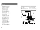
Overview
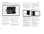
VBS
VBS
REMOTE
REMOTE
CAMERA
CAMERA
GENLOCK
GENLOCK
CCU/CAMERA
CCU/CAMERA
RS232C
RS232C
GEN
LOCK
RETURN
VIDEO
RETURN
VIDEO
PROMPT
VIDEO
PROMPT
VIDEO
RETURN
VIDEO
PROMPT
VIDEO
Y/R–Y/B–Y,R/G/B,Y/C
Y/R–Y/B–Y,R/G/B,Y/C
1)
AC IN
DC IN
1)
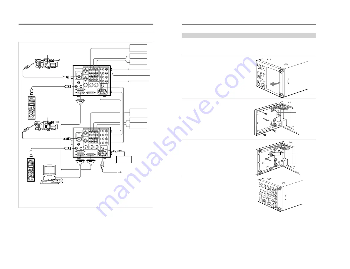
When using two CCU-TX7/TX7P units
CA-TX7/TX7P
DXC-D30/D30P
Triaxial cable
CCA-7 cable
RCP-TX7
CCU-TX7/TX7P
3)
Switcher, video
monitor, etc.
VTR
Chroma keyer
Reference sync signal
Return video signal
Teleprompter signal
(For power sources,
see the connections
illustrated for the unit
shown below.)
DC power
source
2)
AC power source
2)
AC power cord
(supplied)
Personal computer
(When the RCP-TX7s are
not connected.)
1) Y/R–Y/B–Y, R/G/B, and Y/C outputs are switchable.
2) Use either AC or DC power source.
3) This illustration shows the CCU-TX7.
Switcher, video
monitor, etc.
VTR
Chroma keyer
CCU-TX7/
TX7P
3)
CA-TX7/TX7P
DXC-D30/D30P
CCA-7 cable
Triaxial cable
RCP-TX7
6
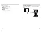
Installing the Camera Operation Unit
The following describes how to fit the optional COU-
TX7 Camera Operation Unit to the CCU-TX7/TX7P’s
front panel.
1
Open the CCU-TX7/TX7P’s
front panel.
2
Remove the blank panel and
the connector cap.
3
Attach the camera operation
unit to the front panel and
connect the flat cable to the
connector.
4
Close the front panel and
fasten the screws.
Stopper
Connector cap
Blank panel
Flat cable
Camera
operation unit
7

