background image

4-14

CCU-TX7 (E)/V1

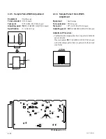
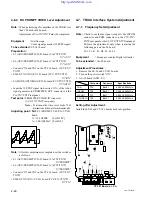
4-3-5. Sample Pulse Width Adjustment

Equipment

:

Oscilloscope

To be extended :

YD-26 board

Test point

:

TP7 (GND: E2)/YD-26 board

Adjusting point :

1

RV4 (SAMPLE S/H)/YD-26 board

Specification

:

T = 40.0 

±

2.0 

µ

s

4-3-6. Sample Pulse V Gate Width

Adjustment

Equipment

:

Oscilloscope

To be extended :

YD-26 board

Test point

:

TP7 (GND: E2)/YD-26 board

Adjusting point :

1

RV3 (SAMPLE GATE)/YD-26 board

Adjustment Procedure :

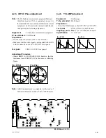
• Confirm that the sample pulses have six pulses in both odd

and even fields.

If not met, adjust 

1

RV3 (SAMPLE GATE)/YD-26 board

so that the sample pulses have six pulses in both odd and

even fields.

V

50%

T

6 Pulses

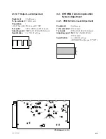
YD-26

YD-26 Board

 (A SIDE)

RV1

Y AGC CONT

RV10

C AGC CONT

S2

CABLE LENGTH

S1

RV2

BLACK S/H

RV5

SYNC S/H

RV6

VCO DC SET

RV12

B-Y LEVEL

RV13

OFFSET ADJ

RV14

PLL SET

RV15

C CAR LEV

RV8

SAMPL S/H

RV4

SAMPL GATE

RV3

B-Y CARR BAL

RV11

TP9

TP16

R-Y CARR BAL

RV16

Y LEVEL

RV9

RV17

R-Y LEVEL

RV18

90° SET

S3

Y 2'nd AGC

S4

C 2'nd AGC

LV1

OFF

ON

OFF

ON

MODE

AUTO

MAN

RV24

RV7

Y CAR LEVEL

Y CARR BAL

Y OFFSET ADJ

Y RF TUNE

TP2

E1

E7

E4

TP15

E3

E2

E8

E5

E6

E9

E16

TP3

TP4 TP7

TP6

TP5

TP13

TP1

TP14

TP26

TP10

TP20

TP21

TP12

TP19

TP11

TP18

TP8

TP17

Содержание CCU-TX7

Страница 1: ...CCU TX7 CAMERA CONTROL UNIT SERVICE MANUAL Vol 1 1st Edition CCU TX7P CAMERA CONTROL UNIT COU TX7 CAMERA OPERATION UNIT ...

Страница 2: ...derselben für irgendeinen anderen Zweck als die Bedienung oder Wartung der in dieser Anleitung beschriebenen Ausrüstung ohne ausdrückliche schriftliche Erlaubnis der Sony Corporation SAFETY CHECK OUT After correcting the original service problem perform the following safety checks before releasing the set to the customer Check the metal trim metallized knobs screws and all other exposed metal part...

Страница 3: ... CAMERA OPERATION UNIT COU TX7 This manual contains the operation manual related to the operations of this equipment the replacement of the parts and adjustments In addition to this Service Manual Vol 1 the following manual is provided Service Manual Vol 2 Part No 9 977 286 21 Contains semiconductor pin assignments parts lists block diagrams board illustrations and schematic diagrams ...

Страница 4: ... Adjustment 4 9 4 2 14 Carrier Balance Adjustment 4 9 4 2 15 Color Vector Adjustment 4 10 4 2 16 R Y B Y OUT Level Adjustment 4 10 4 2 17 VBS OUT Level Adjustment 4 11 4 2 18 STAIR CASE Adjustment 4 11 4 3 Y Cable Compensation System Adjustment 4 12 4 3 1 SYNC SEP Adjustment 4 12 4 3 2 BLACK Pulse Width Adjustment 4 12 4 3 3 SYNC Sample Hold Pulse Width Adjustment 4 13 4 3 4 22 5 MHz VCO DC Set Ad...

Страница 5: ...eviation Adjustment 4 27 4 7 4 INCOM Demodulation Adjustment 4 28 4 7 5 INCOM Level Adjustment 4 28 4 7 6 MIC 1 Demodulation Adjustment 4 29 4 7 7 MIC 1 Level Adjustment 4 29 4 7 8 MIC 2 Demodulation Adjustment 4 30 4 7 9 MIC 2 Level Adjustment 4 30 4 7 10 CAM DATA Demodulation Adjustment 4 31 4 7 11 CAM TONE Adjustment 4 31 http getMANUAL com ...

Страница 6: ...TION 1 OPERATING INSTRUCTIONS Operating Instructions Before operating the unit please read this manual thoroughly and retain it for future reference Camera Control Unit 3 859 845 11 1 CCU TX7 TX7P 1997 by Sony Corporation ...

Страница 7: ...ice pursuant to Part 15 of the FCC Rules These limits are designed to provide reasonable protection against harmful interference when the equipment is operated in a commercial environment This equipment generates uses and can radiate radio frequency energy and if not installed and used in accordance with the instruction manual may cause harmful interference to radio communications Operation of thi...

Страница 8: ...computer to be connected for computer based control of video camera operations Wide array of input output signals The input and output connectors provided for the CCU TX7 TX7P include those for outputting such signals as a composite video signal VBS component video signals switchable to RGB video signals for video and waveform monitors and for inputting a reference signal for external synchronizat...

Страница 9: ...source 2 AC power cord supplied Personal computer When the RCP TX7s are not connected 1 Y R Y B Y R G B and Y C outputs are switchable 2 Use either AC or DC power source 3 This illustration shows the CCU TX7 Switcher video monitor etc VTR Chroma keyer CCU TX7 TX7P 3 CA TX7 TX7P DXC D30 D30P CCA 7 cable Triaxial cable RCP TX7 6 Installing the Camera Operation Unit The following describes how to fit...

Страница 10: ...tton When you press this button it lights along with the red TALLY lamps and CALL buttons on the video camera camera adaptor and remote control panel connected to this unit This function can be used to call the video camera or remote control panel operator You can then talk with the operator via the intercom This button also lights when the CALL button is pressed on the camera adaptor or remote co...

Страница 11: ...ow When SHUTTER switch is set to C SCAN Pressing and holding one of these buttons gradually reduces button or increases 4 button the clear scan frequency When SHUTTER switch is set to ON Each time one of these buttons is pressed the shutter speed is reduced button or increased 4 button by one step If you press both of these buttons at once it resets the clear scan frequency or shutter speed depend...

Страница 12: ...e click position of the knob provides a typical setting 7 GAIN switch Use this switch to set any of three video amp gain levels HIGH MID or LOW The gain value corresponding to these levels can be set using a menu on the video camera 8 TLCS total level control system switch Press this switch to turn the total level control system on or off The switch lights when it is turned on When this switch is ...

Страница 13: ...PUT connectors BNC type R R Y C G Y Y and B B Y component video signal RGB signal Y and C signal output connectors Use these connectors to output component signals R Y B Y and Y R G and B signals for chroma key and Y and C signals Use a switch on an internal board ES 20 to select the type of output signal VBS1 and VBS2 composite video signal 1 and 2 output connectors Use these connectors to output...

Страница 14: ...it on a DC power source the breaker is actuated to shut off the power supply To resume operation push in the breaker switch after making sure the input current does not exceed 10 A 16 Location and Function of Parts CT 181 AA 90 YD 26 ES 20 Internal Board Switches and Knobs Loosen the two screws on the right side of the front panel to expose switches and knobs on the edges of internal boards For de...

Страница 15: ... LEVEL IND indicators INTERCOM switches AA 90 PGM IN LEVEL IND INTERCOM MIC 1 LEVEL 0dB 20dB 0dB 20dB 0dB 20dB RTS CLEAR COM CLEAR COM CH1 CH2 OFF 2W RTS 4W MIC 2 LEVEL MIC TEST 18 Location and Function of Parts INTERCOM intercom system select switches Use these switches to select the type of external intercom system to be used Set the upper switch to 4W if no external intercom is connected If you...

Страница 16: ...mm Operating temperature 5 C to 40 C 41 F to 104 F Mass About 8 45 kg 18 lb 10 oz Dimensions w h d excluding protruding parts 200 164 370 mm 7 7 8 6 1 2 14 5 8 inches Input connectors GENLOCK BNC type 2 loop through VBS BS 1 0Vp p 75 Ω RETURN VIDEO 1 2 BNC type 2 each loop through VBS 1 0 Vp p 75 Ω PROMPT VIDEO BNC type 2 loop through VBS 1 0 Vp p 75 Ω PGM IN XLR 3 pin 1 Output connectors VBS1 VBS...

Страница 17: ...for CCU TX7 300 mV p p for CCU TX7P PIX BNC 1 0 V p p VBS 1 2 BNC 140 IRE SYNC BNC VBS 0 3 V p p negative WF BNC 700 mV p p Encoded output 1 0 V p p R G B Y R Y B Y Y C selection Selectable with S800 S801 on the ES 20 board Input Output signals TRIAX King type for CCU TX7 Fischer type for CCU TX7P COAX BNC MIC OUTPUT CH1 CH2 XLR 3P MALE EXTERNAL VIEW 0 dBu 0 775 Vrms No Signal Specifications 1 MIC...

Страница 18: ...10 4W CH1 R X OUT 23 4W CH1 T G OUT 4W CH1 SYSTEM TALK 11 4W CH1 T Y OUT 0 dBu BALANCED 24 4W CH1 T X OUT 12 2W CH1 G IN OUT 2W CH1 SYSTEM 0 dBu 25 2W CH1 X IN OUT Recommended Term imp 600 Ω 13 CHASIS GND 25 14 1 13 RS 232C CH1 CH2 D Sub 25P FEMALE EXTERNAL VIEW 0 dBu 0 775 Vrms No Signal Specifications 1 CHASSHIS GND This is based on RS 232C 2 TXDATA specification 3 RXDATA 38 400 bps or 9600 bps ...

Страница 19: ...X IN OUT Current drive 3 RTS CH1 X IN OUT Recomended Term lmp 200 Ω DC IN XLR 4P MALE EXTERNAL VIEW No Signal Specifications 1 GND GND for DC 2 SPARE 3 SPARE 4 DC IN DC 10 5 V to 17 V Loop through EXTERNAL VIEW EXTERNAL VIEW FEMALE MALE 2 Front panel INTERCOM XLR 5P FEMALE EXTERNAL VIEW 0 dBu 0 775 Vrms No Signal Specifications 1 INCOM T G IN 60 dBu 2 INCOM T X IN DYNAMIC MIC only 3 NCOM R G OUT G...

Страница 20: ... MALE or CANNON XLR 3 12C or the equivalent INTERCOM TALLY D Sub 25 pin male RS 232C CH1 CH2 JAE DA 25PF N or the equivalent 25P FEMALE WF MODE 1 560 343 11 plug 4 pin male 4P FEMALE REMOTE 1 766 848 11 plug 10 pin male or 10P FEMALE CCA cable assembly CCA 7 5 supplied with RCP TX7 50 m max INTERCOM 1 508 370 11 XLR 5 pin male 5P FEMALE or CANNON XLR 5 12 C or the equivalent 2 1 3 Wiring Diagram f...

Страница 21: ...e CN4 CN4 RF cable CN3 IO 140 board 2 4 OPERATING ENVIRONMENT Operating temperature 5 C to 40 C Storage temperature 20 C to 55 C Humidity Noncondcnsing Supply voltage 100 V to 240 V 10 50 60Hz Power consumption 95 W maximum 1 Do not put the unit in a place subject to high temperature or in a location near hear sources 2 Do not put the unit in a place subject to excessive electrical and magnetic fi...

Страница 22: ...d rack in parallel by using rack mount adaptor RMM TXC7 optional Mounting 1 Tighten the four rack mount screws 2 Mount the CCU TX7 TX7P on the rack mount adaptor as shown in the figure below and tighten the four fixing screws supplied for RMM TXC7 B5 screws 60 mm or more long RMM TXC7 Screws Screws ...

Страница 23: ...X7P In case of using the RX mode RX side 1 Disconnect CN7 and connect CN3 and CN8 on the CT 181 board 2 Set S1 and S6 switches to AUX side on the YD 25 board of CA TX7 TX7P Factory setting TX S2011 R TALLY POWER CONTACT S2013 R TALLY DC24 V TTL These switches are set according to the signal standard of the R TALLY signal input to the INTERCOM TALLY PGM connnector on the CCU rear panel For the rela...

Страница 24: ...nd MIC 2 audio do not mix to the program audio Factory setting OFF S2005 RTS Clear Com This switch sets to RTS or Clear Com position when the S2002 switch sets to RTS position Factory setting RTS S2006 RTS 200 Ω ON OFF This switch sets to ON or OFF position for 200 Ω termination in the RTS system Usually this switch sets to OFF position because the RTS system has 200 Ω termination Factory setting ...

Страница 25: ...1 300 m 2 500 m 3 700 m 4 NOT IN USED S3 Y ch 2nd AGC ON OFF S4 CHROMA ch 2nd AGC ON OFF These switches are used for RF AGC adjustment Usually set these switches to ON YD 26 YD 26 Board A SIDE RV1 Y AGC CONT RV10 C AGC CONT S2 CABLE LENGTH S1 RV2 BLACK S H RV5 SYNC S H RV6 VCO DC SET RV12 B Y LEVEL RV13 OFFSET ADJ RV14 PLL SET RV15 C CAR LEV RV8 SAMPL S H RV4 SAMPL GATE RV3 B Y CARR BAL RV11 TP9 T...

Страница 26: ...tory setting 0 S800 OUTPUT 1 SELECT R G B Y R Y B Y Y C This switch selects the signals of the G R B Y R Y B Y and Y C to output the OUTPUT 1 connectors on the CCU rear panel Factory setting R Y Y B Y ES 20 ES 20 Board A SIDE RV511 R DC BAL R MAT BAL RV509 R Y GAIN RV502 R Y BLK BAL RV501 G MAT BAL2 RV506 B WHT BAL RV505 R WHT BAL RV500 RV507 G MAT BAL1 RV504 B Y GAIN ADJ RV503 B Y BLK BAL B MAT B...

Страница 27: ...ORMATION CN 1325 board CN 1328 board CN 1351 board CN 1327 board IO 140 board MB 693 board CT 181 board AA 90 board YD 26 board ES 20 board CN 1350 board Switching regulator AU 234 board Loosen two coin screws Front panel 2 2 Removal of Cover Connector Front panel Connector Step shaft K 3x6 AU 234 board Top cover B 3x5 B 3x5 B 3x5 B 3x5 Bottom cover ...

Страница 28: ...d CN20 on the MB 693 board Remove the rear panel 3 Remove six screws and switching regulator 4 When installing a new switching regulator reverse the above procedures CN1 CN10 MB 693 board CN19 CN20 K 3x6 K 3x6 Rear panel IO 140 board Switching regulator B 4x5 B 4x5 B 4x5 3 2 3 Installation of COU TX7 As for installing of COU TX7 refer to Installing the Camera Operation Unit of service manual SECTI...

Страница 29: ... modulation circuit becomes AUX VIDEO demodulation circuit by switching S2002 and connecting RF coaxial cable to CN3 and CN8 It is needed to change on the YD 25 board of CA Demodulated AUX VIDEO is outputted from PROMPT VIDEO on the rear panel AA 90 board This board demodulates the RF signal of MIC1 MIC2 INCOM CAM DATA and TONE sent from the CA modulates a PGM signal the INCOM signal and control d...

Страница 30: ...ustment connect the WF MODE connector of CCU TX7 TX7P rear panel to the remote control connector of waveform monitor with the connecting cord Refer to Section 2 2 2 Making of WF MODE Connection Do not turn the following adjusting core on the YD 26 and CT 181 boards Replace a new one when a filter is faulty Filters on the YD 26 board and CT 181 board FL1 FL2 FL4 FL5 FL6 FL7 FL8 FL9 FL10 FL11 FL12 F...

Страница 31: ...7P TRIAX CABLE 30 750m CCA TX7 CABLE CAMERA CONTROL UNIT CCU TX7 TX7P CAMERA OPERATION UNIT COU TX7 TX7P PIX 75Ω CAMERA ADAPTOR CA TX7 TX7P A ch Vector scope Color monitor Waveform monitor RCP TX7 75Ω 600Ω 600Ω GND GND Y X LEVEL ADJ Fig 1 Fig 2 Audio generator Audio generator GND GND X LEVEL ADJ ...

Страница 32: ...1RV1 CAM H PHASE ES 20 board Specification T 0 0 05 µs T 50 50 CH1 CH2 ES 20 ES 20 Board A SIDE RV511 R DC BAL R MAT BAL RV509 R Y GAIN RV502 R Y BLK BAL RV501 G MAT BAL2 RV506 B WHT BAL RV505 R WHT BAL RV500 RV507 G MAT BAL1 RV504 B Y GAIN ADJ RV503 B Y BLK BAL B MAT BAL RV512 RV1000 LEVEL RV514 B DC BAL RV513 B LEVEL RV510 R LEVEL G LEVEL RV7 H PHASE RV6 SC PHASE S1 S3 SC 0 180 S800 OUTPUT 1 SEL...

Страница 33: ...te white portion of the pattern box Equipment Waveform monitor To be extended ES 20 board Preparation Adjust the zoom control at TELE so that the white pattern feame matches the underscanned picture frame on the screen In case of RCP TX7 IRIS AUTO Button Control panel ON In case of COU TX7 IRIS AUTO MANUAL switch Control panel AUTO Test point VBS 1 OUT connector CCU rear panel Adjusting point 1RV2...

Страница 34: ...ing figure Note After this adjustment is completed set the mode of Tektronix Waveform monitor 1765 to WFM mode A For NTSC For PAL A ES 20 ES 20 Board A SIDE RV511 R DC BAL R MAT BAL RV509 R Y GAIN RV502 R Y BLK BAL RV501 G MAT BAL2 RV506 B WHT BAL RV505 R WHT BAL RV500 RV507 G MAT BAL1 RV504 B Y GAIN ADJ RV503 B Y BLK BAL B MAT BAL RV512 RV1000 LEVEL RV514 B DC BAL RV513 B LEVEL RV510 R LEVEL G LE...

Страница 35: ...100 2 IRE SYNC Level Adjustment 1RV801 B 40 1 IRE SET UP Level Adjustment 1RV800 C 7 5 1 IRE ES 20 board For PAL Adjusting point Specifications Y Level Adjustment 1RV802 A 700 10 mV SYNC Level Adjustment 1RV801 B 300 5 mV ES 20 ES 20 Board A SIDE RV511 R DC BAL R MAT BAL RV509 R Y GAIN RV502 R Y BLK BAL RV501 G MAT BAL2 RV506 B WHT BAL RV505 R WHT BAL RV500 RV507 G MAT BAL1 RV504 B Y GAIN ADJ RV50...

Страница 36: ... mV p p 1RV504 3 Repeat procedure 1 and 2 several times 4 2 10 G Level Adjustment Equipment Waveform monitor To be extended ES 20 board Preparation Select the BARS mode on the RCP TX7 or COU TX7 S800 R G B Y R Y B Y Y C ES 20 board R G B Adjustment Procedure 1 Test point G Y Y1 OUT connector CCU rear panel Adjusting point 1RV507 G MAT BAL1 ES 20 board 1RV506 G MAT BAL2 ES 20 board Specification A ...

Страница 37: ...ication B 700 10 mV For NTSC B 700 10 mV For PAL A A For NTSC For PAL For NTSC For PAL B B 7 _0 7 _0 7 _0 7 _0 ES 20 ES 20 Board A SIDE RV511 R DC BAL R MAT BAL RV509 R Y GAIN RV502 R Y BLK BAL RV501 G MAT BAL2 RV506 B WHT BAL RV505 R WHT BAL RV500 RV507 G MAT BAL1 RV504 B Y GAIN ADJ RV503 B Y BLK BAL B MAT BAL RV512 RV1000 LEVEL RV514 B DC BAL RV513 B LEVEL RV510 R LEVEL G LEVEL RV7 H PHASE RV6 S...

Страница 38: ...even after the MONITOR SELECT button RCP TX7 is selected R G and B Specification DC level 1 mV G 4 2 14 Carrier Balance Adjustment Equipment Vectorscope MAX GAIN To be extended ES 20 board Preparation Select the BARS mode on the RCP TX7 or COU TX7 Test point VBS 1 OUT connector CCU rear panel Adjustment Procedure Adjust 1RV805 I V CAL and 1RV809 Q U CAL ES 20 board so that the luminance point of b...

Страница 39: ...5 Color Vector Adjustment Equipment Vectorscope Waveform monitor To be extended ES 20 board Preparation GAIN Switch vectorscope 75 CAL Adjust the PHASE control on the vectorscope so that the burst spot is aligned to the 75 axis Select the BARS mode on the RCP TX7 or COU TX7 Test point VBS 1 OUT connector CCU rear panel Adjustment Procedure 1 Adjust 1RV806 BURST LEVEL ES 20 board so that the burst ...

Страница 40: ... 1 V p p 1RV1001 B 0 1 V dc 1RV1000 A A For NTSC For PAL B GND A ES 20 Board A SIDE ES 20 RV511 R DC BAL R MAT BAL RV509 R Y GAIN RV502 R Y BLK BAL RV501 G MAT BAL2 RV506 B WHT BAL RV505 R WHT BAL RV500 RV507 G MAT BAL1 RV504 B Y GAIN ADJ RV503 B Y BLK BAL B MAT BAL RV512 RV1000 LEVEL RV514 B DC BAL RV513 B LEVEL RV510 R LEVEL G LEVEL RV7 H PHASE RV6 SC PHASE S1 S3 SC 0 180 S800 OUTPUT 1 SELECT OU...

Страница 41: ...uipment Oscilloscope To be extended YD 26 board Test point TP5 GND E2 YD 26 board Adjusting point 1RV2 BLACK S H YD 26 board Specification T 1 7 0 1 µs A H T 50 H YD 26 YD 26 Board A SIDE RV1 Y AGC CONT RV10 C AGC CONT S2 CABLE LENGTH S1 RV2 BLACK S H RV5 SYNC S H RV6 VCO DC SET RV12 B Y LEVEL RV13 OFFSET ADJ RV14 PLL SET RV15 C CAR LEV RV8 SAMPL S H RV4 SAMPL GATE RV3 B Y CARR BAL RV11 TP9 TP16 R...

Страница 42: ...usting point 1RV5 SYNC S H YD 26 board Specification T 1 3 0 1 µs 4 3 4 22 5 MHz VCO DC Set Adjustment Note Make sure that 45MHz frequency on the YM 15 board CA TX7 TX7P should be correct Equipment Oscilloscope To be extended YD 26 board Test point TP9 GND E2 YD 26 board Adjusting point 1RV6 VCO DC SET YD 26 board Specification A 0 30 mV dc T 50 GND A ...

Страница 43: ... fields If not met adjust 1RV3 SAMPLE GATE YD 26 board so that the sample pulses have six pulses in both odd and even fields V 50 T 6 Pulses YD 26 YD 26 Board A SIDE RV1 Y AGC CONT RV10 C AGC CONT S2 CABLE LENGTH S1 RV2 BLACK S H RV5 SYNC S H RV6 VCO DC SET RV12 B Y LEVEL RV13 OFFSET ADJ RV14 PLL SET RV15 C CAR LEV RV8 SAMPL S H RV4 SAMPL GATE RV3 B Y CARR BAL RV11 TP9 TP16 R Y CARR BAL RV16 Y LEV...

Страница 44: ...e OFF 4 3 8 Y DEMOD Carrier Balance Adjustment Equipment Oscilloscope To be extended YD 26 board Preparation In case of RCP TX7 Set IRISAUTO button to OFF and close the lens iris by IRIS control knob In case of COU TX7 Set AUTO MANUAL switch to MANUAL and close the lens iris by IRIS control knob S3 Y 2nd AGC YD 26 board OFF Test point TP11 GND E6 YD 26 board Adjusting point 1RV8 Y CARR BAL YD 26 b...

Страница 45: ...ard Preparation Select the BARS mode on the RCP TX7 or COU TX7 Test point TP26 GND E6 YD 26 board Adjusting point 1FL3 90 SIFT YD 26 board Specification A 0 10 mV 4 3 11 Y 1st AGC Adjustment Equipment Oscilloscope To be extended YD 26 board Preparation S1 AUTO MANU YD 26 board AUTO S3 Y 2nd AGC YD 26 board OFF Test point TP11 GND E6 YD 26 board Adjusting point 1RV1 Y AGC CONT YD 26 board Specifica...

Страница 46: ...oint 1RV15 C CARR LEVEL YD 26 board Specification A 400 20 mV p p BW LIMIT Oscilloscope OFF A A YD 26 YD 26 Board A SIDE RV1 Y AGC CONT RV10 C AGC CONT S2 CABLE LENGTH S1 RV2 BLACK S H RV5 SYNC S H RV6 VCO DC SET RV12 B Y LEVEL RV13 OFFSET ADJ RV14 PLL SET RV15 C CAR LEV RV8 FL3 SAMPL S H RV4 SAMPL GATE RV3 B Y CARR BAL RV11 TP9 TP16 R Y CARR BAL RV16 Y LEVEL RV9 RV17 R Y LEVEL RV18 90 SET S3 Y 2 ...

Страница 47: ...point 1RV11 B Y CARR BAL YD 26 board Specification Adjust so that the waveform level of SAMPLE pulse is maximum A GND V Maximum YD 26 YD 26 Board A SIDE RV1 Y AGC CONT RV10 C AGC CONT S2 CABLE LENGTH S1 RV2 BLACK S H RV5 SYNC S H RV6 VCO DC SET RV12 B Y LEVEL RV13 OFFSET ADJ RV14 PLL SET RV15 C CAR LEV RV8 SAMPL S H RV4 SAMPL GATE RV3 B Y CARR BAL RV11 TP9 TP16 R Y CARR BAL RV16 Y LEVEL RV9 RV17 R...

Страница 48: ...oard Test point TP17 GND E8 YD 26 board Adjusting point 1RV13 OFFSET ADJ YD 26 board Specification A 0 3 mV 4 4 5 C 1st AGC Adjustment Equipment Oscilloscope To be extended YD 26 board Preparation S1 AUTO MANU YD 26 board AUTO S4 C 2nd AGC YD 26 board OFF Test point TP17 GND E8 YD 26 board Adjusting point 1RV10 C AGC CONT YD 26 board Specification A 350 20 mV SYNC A BLKG A ...

Страница 49: ...cification Adjust 1RV16 so that the negative DC level is maximum A GND Negative DC level Maximum YD 26 YD 26 Board A SIDE RV1 Y AGC CONT RV10 C AGC CONT S2 CABLE LENGTH S1 RV2 BLACK S H RV5 SYNC S H RV6 VCO DC SET RV12 B Y LEVEL RV13 OFFSET ADJ RV14 PLL SET RV15 C CAR LEV RV8 SAMPL S H RV4 SAMPL GATE RV3 B Y CARR BAL RV11 TP9 TP16 R Y CARR BAL RV16 Y LEVEL RV9 RV17 R Y LEVEL RV18 90 SET S3 Y 2 nd ...

Страница 50: ...oard Test point TP19 GND E9 YD 26 board Adjusting point 1RV18 90 SET YD 26 board Specification The SAMPLE pulse level should be minimum A 0 3 mV 4 4 9 R Y OUT Level Adjustment Equipment Oscilloscope To be extended YD 26 board Preparation S4 C 2nd AGC YD 26 board ON Test point TP19 GND E9 YD 26 board Adjusting point 1RV17 R Y LEVEL YD 26 board Specification A 350 5 mV A V A ...

Страница 51: ...ation T 2 000 0 005 MHz Note Performe the adjustment of 4 5 1 Return Video Carrier Frequency Adjustment when the SYNC portion is moved during the adjustment SYNC 69 0MHz CENT FREQ 69 0MHz FFEQ SPAN 5 0MHz 69 0MHz CENT FREQ 69 0MHz FFEQ SPAN 5 0MHz T CT 181 MIC GAIN PANEL R TALLY CONTACT POWER DC24V TTL CT 181 Board A SIDE G TALLY CONTACT POWER DC24V REMOTE LOCAL CONTROL MODE NORMAL SLAVE TTL CH 1 ...

Страница 52: ...CN7 and CN3 on the CT 181 board CCU TX7 TX7P S2002 TX RX CT 181 board CCU TX7 TX7P TX S1 MODEAUTO MAN YD 26 board CCU TX7 TX7P AUTO Input 10 STEP signal sub carrier OFF of video signal generator to PROMPT VIDEO IN connector 75 Z termination 1 0 V p p on the CCU TX7 TX7Prear panel Test point PROMPTER OUT CA TX7 TX7P Note To measure the video level make 75 Z termination on the waveform monitor side ...

Страница 53: ...acing 1LV2 PROMPT FREQ or 1LV3 PROMPT TUNE CT 181 board When performing this adjustment the TRIX cable less than 300 m should be used Adjustment of CA TX7 TX7P must be completed Equipment Waveform monitor Video signal generator 10 STEPsignal To be extended CT 181 board Preparation S1 AUX PROMPT YD 25 board CA TX7 TX7P AUX S6 AUX PROMPT YD 25 board CA TX7 TX7P AUX Connect CN8 and CN3 on the CT 181b...

Страница 54: ...ctor CCU TX7 TX7P rear panel Note To measure the video level make 75 Z termination on the waveform monitor side Adjusting point 1RV22 RF AGC DLY CT 181 board Adjustment Procedure Turn 1RV22 RF AGC DLY CT 181 board fully in the clockwise direction and then turn it slowly in the counterclockwise direction so that the V SYNC position of waveform becomes flat Take care not to over turn CT 181 MIC GAIN...

Страница 55: ...X7P S2002 TX RX CT 181 board CCU TX7 TX7P RX S1 MODEAUTO MAN YD 26 board CCUTX7 TX7P AUTO Input the 10 STEP signal sub carrier ON of the video signal generator to PROMPTER OUT connector on the CA TX7 TX7P real panel Test point PROMPTER VIDEO IN connector CCU TX7 TX7P rear panel Note To measure the video level make 75 Z termination on the waveform monitor side Adjusting point 1RV23 PROMPT LEVEL CT ...

Страница 56: ...AA 90 board CCU TX7 TX7P 4W 4 Input the 400 Hz sine wave signal of the audio generator to pin 84 X pin 83 Y and pin 82 GND extension board AA 90 board Fig 2 Refer to 4 1 5 Audio connection 5 Adjust the output level of audio generator so that the level at TP43 GND E10 AA 90 board is 220 mVp p Test point TP3 GND E1 AA 90 board Adjustment point 1RV41 INCOM DEV AA 90 board Specifications A B 6 0 0 2 k...

Страница 57: ...uipment Oscilloscope Audio generator To be extended AA 90 board FM 15 board CA TX7 TX7P Preparetion 1 Input the 1 kHz sine wave signal of the audio generator to pin 2 GND pin 1 of INTERCOM PROGRAM connector 5 pin on the CA TX7 TX7P Fig 1 Refer to 4 1 5 Audio connection 2 Adjust the output level control of audio generator so that the pin 24 GND pin 12 AFM 15 board is 220 mV p p Test point TP15 GND ...

Страница 58: ...tion Adjustment Note Perform this adjustment only when replacing1T201 AA 90 board Equipment Oscilloscope Audio generator To be extended AA 90 board Preparations 1 AUDIO SELECT switch CAMERA CA MIC CA LINE CA TX7 TX7P rear panel CA LINE 2 Input the 1 kHz sine wave signal of the audio generator to CH 1 of MIC IN rear panel on the CA TX7 TX7P Fig 2 Refer to 4 1 5 Audio connection 3 Adjust the output ...

Страница 59: ...ope Audio generator To be extended AA 90 board AFM 15 board CA TX7 TX7P Preparations 1 AUDIO SELECT switch CAMERA CA MIC CA LINE CA TX7 TX 7P CA LINE 2 Input the 1 kHz sine wave signal of audio generator to CH 2 of MIC IN rear panel on the CA TX7 TX7P Fig 2 Refer to 4 1 5 Audio connection 3 Adjust the output level control of audio generator so that the pin 17 GND pin 12 AFM 15 board is 220 mV p p ...

Страница 60: ...terclockwise and stop it at the point where the sine wave signal just appears Measure the DC voltage b Fig 2 4 Adjust the DC level with 1RV101 TONE TUNE AA 90 board so that a is equal to b Fig 3 fig 2 Equal a Equal b Turn slowly counterclockwise fig 3 Equal a Equal b A B RV101 A B fig 1 Equal a Turn slowly clockwise Mechanical center 4 7 10 CAM DATA Demodulation Adjustment Notes This adjustment fo...

Страница 61: ...CCU TX7 UC Printed in Japan CCU TX7P CE 1997 6 11 9 977 286 11 1997 Published by Engineering Services Dept Sony Corporation Image Sound Communication Company ...

Отзывы: