4-1
CCU-TX7 (E)/V1
4-1. Preparation
4-1-1. Equipment Required
• Oscilloscope (more than 300 MHz)
Tektronix 2465 or equivalent
• Waveform monitor/Vectorscope
Tektronix 1765 or equivalent
• Color monitor Sony PVM-1354Q or equivalent (For NTSC)
Sony PVM-1454QM or equivalent (For PAL)
• Video signal generator
Tektronix 1410 or equivalent (For NTSC)
Tektronix 1411 or equivalent (For PAL)
(Color Bar signal, 10 STEP signal,
SWEEP signal)
• Video camera
Sony DXC-637 or
DXC-D30 (NTSC)
Sony DXC-637P or DXC-D30P (PAL)
• Remote control Unit
Sony RCP-TX7
(or COU-TX7 : Camera Operation Unit)
• Digital voltmeter
• Frequency counter
• Audio generator
• Spectrum analyzer
• TRIAX Cable
4-1-2. Fixture
Extension board
Extension board
EX-564 (For CCU-TX7/TX7P)
EX-565 (For CA-TX7)
Sony part number :
Sony part number :
J-6276-420-A
J-6276-430-A
Pattern box PTB-500
Sony part number :
J-6029-140-B
• Light source for test chart
4-1-3. Notes on Adjustment
CAUTION
• When performing STAIR CASE adjustment, connect the
WF MODE connector of CCU-TX7/TX7P rear panel to
the remote control connector of waveform monitor with
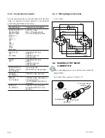
the connecting cord. (Refer to Section 2, 2-2. "Making of
WF MODE Connection")
• Do not turn the following adjusting core on the YD-26 and
CT-181 boards.
Replace a new one when a filter is faulty.
Filters on the YD-26 board and CT-181 board
FL1, FL2, FL4, FL5, FL6, FL7, FL8, FL9, FL10, FL11,
FL12, FL13, FL14, FL15
The adjustment is not required after replacing.
4-1-4. Switch settings
When switching the following switches from a customer-set
position, it is recommended to record the setting state of the
customer in the table below.
After adjustment is complete, be sure to return the switches
to their customer-set position.
Board
Switch
Setting during
Customer-set
adjustment
position
CT-181
S1000
All OFF
S1001
REMOTE
S1002
NORMAL
S1004
All RS-232C side
S2002
TX
S2011
POWER
S2012
POWER
S2013
DC 24 V
S2014
DC 24 V
AA-90
S201
0 dBu
S301
0 dBu
S2002
4W
S2003
2CH
S2004
OFF
S2005
RTS
S2006
OFF
S2081
0 dBu
YD-26
S1
AUTO
S2
0
S3
ON
S4
ON
ES-20
S1
20H (NTSC only)
S2
⋅⋅⋅
S3
0
°
S800
R-Y/Y/B-Y
S801
R-Y/Y/B-Y
S1000
+
SECTION 4
ADJUSTMENT


