


Subject to change | © 2019 SOLARWATT GmbH | AZ-TM-PMS-1339 | Rev 001 | Version: 12/2019
Page 19
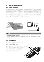
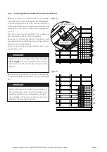
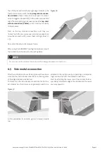
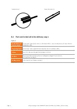
Transitions from one aluminum guide rail to the others
are made in the counter batten area.
Figure 15
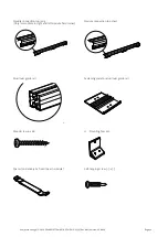
Aluminum guide
rail
Fastening plate
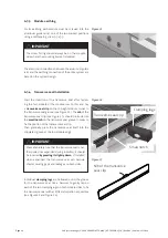
The counter battens under the fastening plates are also
to be fixed with 4 flat-head screws 6 x 80 (see Figure 16).
Figure 16
Flat-head screw 6 x 80
Wood screws
6 x 60
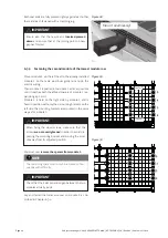
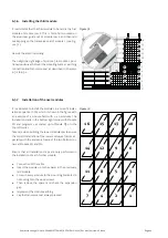
6.2.8 Laying battens for further module rows
For the battening of module row 2, the top of the already
laid aluminum guide rail 6 of module row 1 is used as a
reference surface.
Battens 12, 13, 14, 15 and aluminum guide rail 16 are
to be arranged in the same way and must be fastened as
described in Chapters 6.2.6 to 6.2.7.
Complete the module field in the same way for all other
module rows up to the aluminum guide rail on the top
module field end.
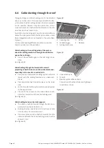
6.2.9 Laying battens for further the top enclo-
sure frame and batten O
Lay the battens for the top enclosure frame according to
the information provided by the supplier of your enclo-
sure frame. When using the SOLARWATT roofing frame
the measurements for the roofing frame are stated in the
installation instructions.
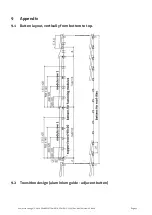
Batten O is positioned with a total distance D to batten U
(see Chapter 5.3).


