


Subject to change | © 2019 SOLARWATT GmbH | AZ-TM-PMS-1339 | Rev 001 | Version: 12/2019
Page 9
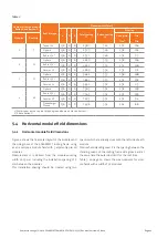
General conditions to be observed
●
The system has only been tested with the materials
stated in System Components (see Chapter 8) and is
therefore only approved for these.
●
To ensure sufficient ventilation counter battens must
be used.
●
The sarking membrane supplied must be used as
mandatory.
●
Max. rafter spacing: 1 m; max. building height: 18 m;
max. wind load zone: 2; max. snow load zone: 3 and
max. 530 meters above sea level (or equivalent): H
and I (according to DIN 1055).
5
Preparation and planning
Use the planning tool provided on www.solarwatt.de to
create a layout plan for the entire roof. This must include
eaves, the module field, ridge and tile cover, along with
any other features of the building such as skylights or
dormers.
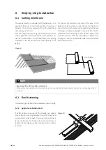
5.1 Eaves
The configuration in the eaves area is an important
pre-condition for the installation of the module field (e.g.
accessibility). Therefore you must plan and implement
this carefully and in accordance with the technical rules
of the German Roofing Trade (ZVDH) and the roof struc
-
ture chosen. As specified in the EasyIn planning sheet the
minimum spacing between module field and eave must
be complied with for the following reasons:
●
Increased wind load at the roof edges
●
Construction of a functioning water drain to avoid
water pockets forming, backfill and overspilling rain
-
water.
5.2 Ridge
The ridge area must include sufficient space so as to
comply with the minimum spacing between the topmost
module edge and/or roofing frame and ridge as stated in
the EasyIn planning sheet.
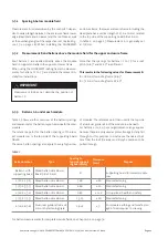
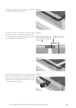
5.3 Batten layout, vertically from bottom to top.
For clarity purposes the substructure below is first dis
-
played in the vertical, and then in the horizontal instal-
lation orientation (see chapter Figure 2 on page 9).
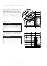
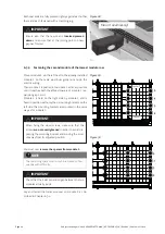
In Figure 3 on page 10 the vertical system configura
-
tion for 2 module rows is displayed (there is an enlarged
image of Figure 3 in Chapter 9.1 on page 33).
The top part shows the requisite layout of the battens for
the layout and the fastening of the modules and the roof-
ing frame.
The bottom part shows the layout of the battens for the
roof tiles which are laid with a standardized batten spac-
ing (LA) next to the module field.
The two areas are connected via the continuous battens U
below, and O above, the module field and which also run
in the roof tile area.
Figure 2