NETYS RT 5 - 7 - 9 - 11 kVA - 551570A - SOCOMEC
34
EN
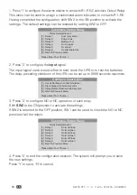
1. Press ‘1’ to configure the alarms relative to contacts R1~R6 (Customize Output Relay).
This menu can be used to assign a customized alarm indication to contacts R1~R6.
Having completed the configuration, shift SW2 to the ON position to activate the
settings. The default settings can be restored by setting SW2 to OFF.
Customize Output Relay
Relay Selected Event
[1] . Relay 1:
Summary Alarm
[2] . Relay 2:
Power Fail
[3] . Relay 3:
Battery Low
[4] . Relay 4:
On by-pass
[5] . Relay 5:
Overload
[6] . Relay 6:
Overtemperature
[0] . Back to Previous Menu
Please Enter Your Choice >
2. Press ‘2’ to configure the
input
signal.
The input signal can be used either to shut down the UPS or to test the batteries.
The delay preceding shutdown of the UPS can be set up to 9999 seconds maximum.
Configure Input Signal
[1] . Act as Shutdown or Test: Shutdown
[2] . Input Signal Confirm 3 Seconds
[3] . Delay Before Shutdown 30 Seconds
[0] . Back to Previous Menu
Please Enter Your Choice >
3. Press ‘3’ to configure NO or NC operation of each relay.
Shift
SW2
to the ON position to activate the settings.
If SW2 is returned to the OFF position, SW1 can be used to check the NO or NC
position of all the relays.
Customize Output Relay
Relay Selected Event
[1] . Relay 1:
Normal Close
[2] . Relay 2:
Normal Open
[3] . Relay 3:
Normal Close
[4] . Relay 4:
Normal Open
[5] . Relay 5:
Normal Close
[6] . Relay 6:
Normal Open
[0] . Back to Previous Menu
Please Enter Your Choice >
4. Press ‘0’ to end the configuration session. The system will prompt you to save
the new settings.
Press ‘Y’ to save, ‘N’ to cancel.
Содержание NETYS RT 1100 VA
Страница 1: ...5000 7000 9000 11000 VA NETYS RT INSTALLATION AND OPERATING MANUAL EN www socomec com netys manuals ...
Страница 2: ......
Страница 103: ......

