MENTOR 12 USER’S MANUAL
SECTION 3: ADVANCED CONTROL – Page 56
However, only the first valid trip that occurs, which is the first
after initiating the Fault state, will stop the test and change
(after the switch time, if any) to the post-fault state.
Two times appear on the actual graphic. One is the time that
has elapsed from the start of the function until the valid trip
and the other is the time that has elapsed from the start of the
Fault state to the valid trip indicated of the relay being tested.
This latter time is considered as the final result of the
function.
The test results are shown on the window situated under the
graphic. Here the times of ALL the trips that have occurred
are indicated, measured from the start of the relative state
where it occurred, as well as the total execution time of the
function indicated by the “END” tag. That is, if there is a trip in
pre-fault, the time indicated on the screen will be from the
moment when it began with the pre-fault, if there is a trip in
the fault, from the moment the fault state began and, if there
is a trip in the post-fault, from the moment when the post-fault
state started.
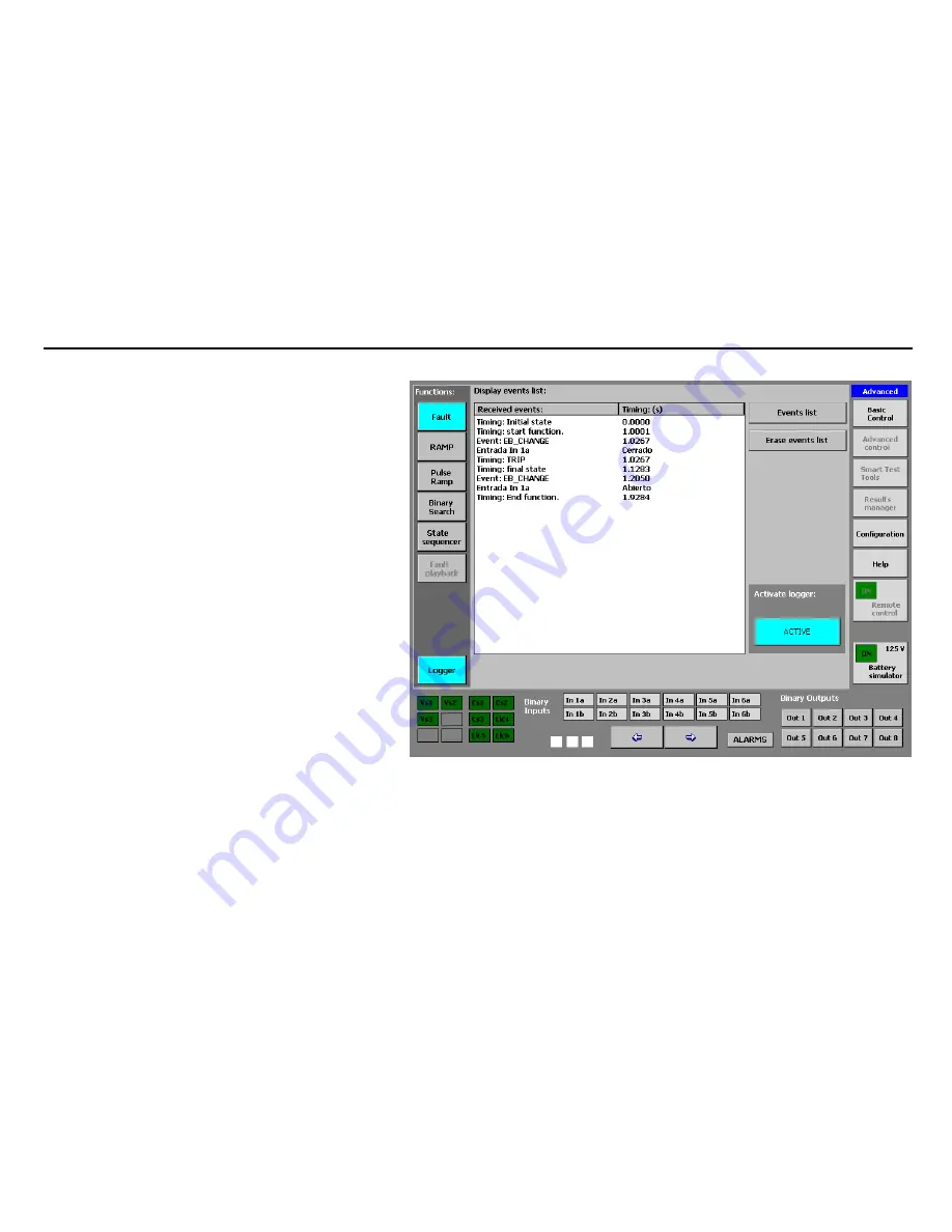
Furthermore, to record and identify the test results better, a
key appears in the lower left-hand corner which says
“Logger”. If you press this key, you can see absolutely all the
digital events that have occurred during the function
execution, with their relative identification and time tag. (See
LOGGER).


