background image

MENTOR 12 USER’S MANUAL 

SECTION 2: BASIC CONTROL – Page 32 


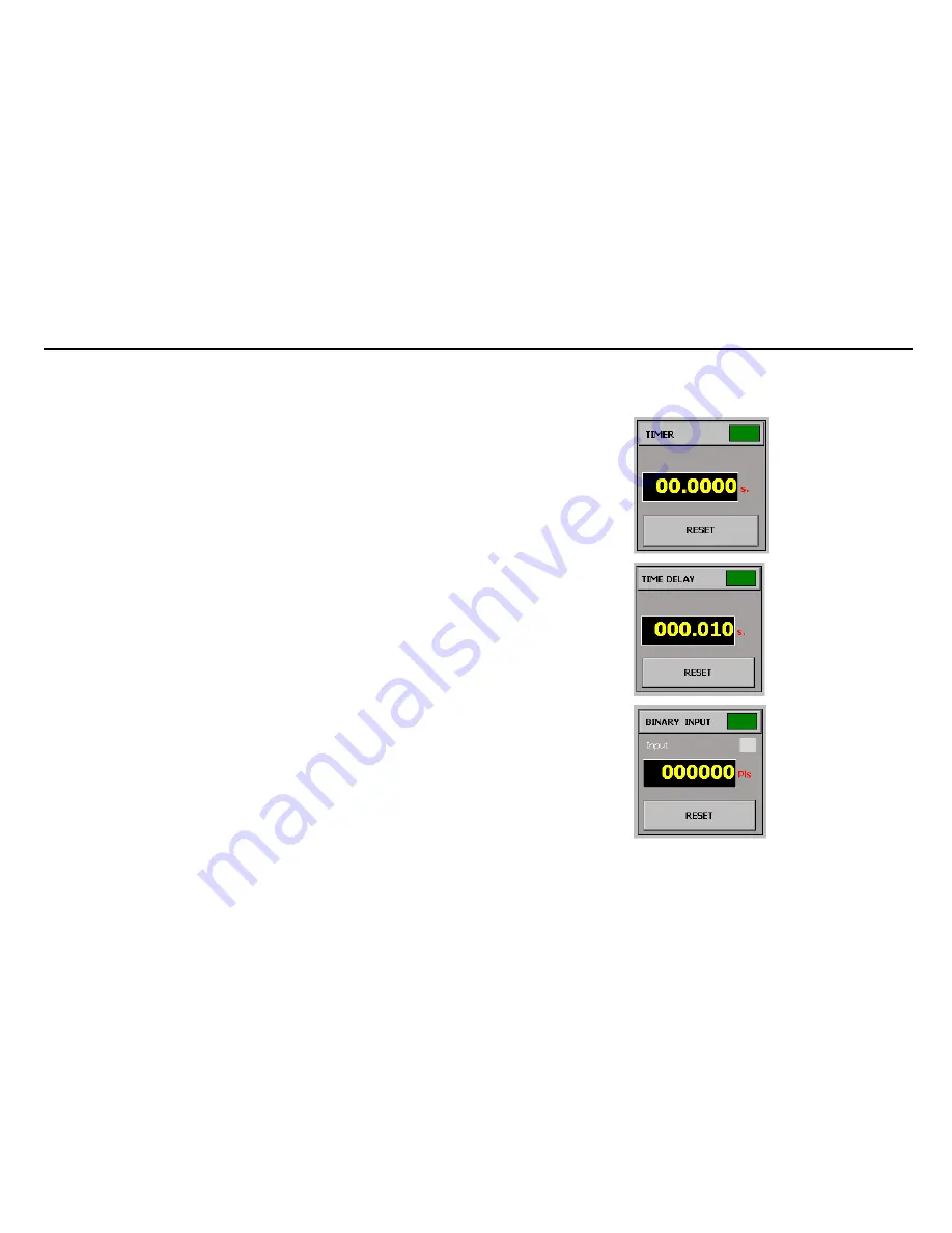
Measurement Window 

There is a section on the Basic Control panel that contains a window, which shows the 
values measured of different magnitudes in real time. The following magnitudes are 
available: 


Trip time in seconds (timer function):

 This measures the time elapsed 

between two events and presents the measurement on the window. Their 
selection and configuration (start and stop) are described further on in this 
manual. The units may be “seconds” or “cycles” (See configuration section).  


Duration of the output in seconds (time delay function).

 It maintains both 

the power outputs and the digital outputs during the time indicated on the 
window. The selection of the time value and the selection of the simultaneous 
actions with the end of count are described further on in this manual. The 
units may be “seconds” or cycles” (See configuration section). 


Value of the magnitude measured through the analogue measurement 
input

 (configurable units) 


Value of the 

number of pulses or frequency

 measured through the logic 

inputs that can work as counters, (configurable units) 

As you can see in the figure, the measurement window is divided into two sections: 


The upper section where the name of the measurement function selected and 
a green or red colored indicator appear. The function is not active when the 
indicator is green and active when the indicator is red. If you press the 
indicator the status of the measuring device changes in cycles. 


The bottom section where the measurement appears. The measurement unit 
used also appears after the digits. If you press the measurement window, the 
parameter, to be measured in cycles, changes, out of those mentioned 

above. The 

Reset

 button only appears with the time and pulse counter 

parameters. If you press this button the window resets to zero and is ready for 
a new measurement cycle. 

Содержание mentor 12

Страница 1: ......

Страница 2: ...the right to change the characteristics of the product and the contents of this document with no previous announcement The user of the product is the only responsible of any consequences from the use...

Страница 3: ......

Страница 4: ...Start up process 12 Start up process 13 Initial check 15 Quick Start 17 Power output control and regulation 17 Monitoring the binary input 18 Binary output control 18 Battery simulator setup and cont...

Страница 5: ...of the function and help keys 26 Select all key 27 Reset Values key 27 Rotate key 28 Save and Rest keys 28 Config Status 2 and Status 2 keys 30 Measurement Window 32 Configure times 33 TIMER START con...

Страница 6: ...Configuration 66 Execution 71 BINARY SEARCH Function 73 Configuration 75 Execution 79 STATE SEQUENCER function 81 Configuration 82 Execution 84 SECTION 4 CONFIGURATION 87 Introduction 87 Common Confi...

Страница 7: ...SECTION 1 PRODUCT INTRODUCTION Page 7 Binary Outputs 94 Definitions 94 Usage Procedure 95 Binary Inputs 96 Definitions 96 Usage Procedure 97 Miscellaneous 99 Definitions and Use 100 Maintenance 103 D...

Страница 8: ...connected to the power supply CAUTION Turn the unit ON before cabling anything to the connection s board Most input and output connectors in this board are dynamic and feature self protecting mechanis...

Страница 9: ...f test leads in a nylon bag 1 Twisted pair ETHERNET LAN cable 1 External mouse keyboard PS 2 cord 1 User s documentation 1 Certificate of calibration 1 Transportation hard case with wheels NOTE Conten...

Страница 10: ...und before opening it CAUTION Do not grab the unit by the touch panel Slide one hand into the slot underneath the touch panel and grab the back of the unit with the other hand to lift the unit off the...

Страница 11: ...n Do not operate the unit on soft carpets cushioned or similar types of surface that can block the normal ventilation air flow Sand or excessive dust can get into the unit and cause serious ventilatio...

Страница 12: ...een TFT panel swivel Adjustment knob Handle Main FUSE BATTERY simulator Power VOLTAGE outputs Power CURRENT outputs COMMUNICATIONS set GPS antenna plug Analogue MEASUREMENT BINARY INPUT BINARY OUTPUT...

Страница 13: ...The start up process takes less than 2 minutes and includes General hardware check Embedded PC start up test initialization Specific hardware check Mentor Application start up Upon completion of the s...

Страница 14: ...ction area Output source phase angle Output source level display Output source level range frequency bus Output source ON OFF Battery Simulator setup area Measurements window Binary Output ON OFF butt...

Страница 15: ...irm that it has been configured properly according to your specifications This will take you less than 5 minutes NOTE The procedures below assume that the Mentor 12 is in its initial power on state i...

Страница 16: ...of your particular unit FREQUENCY Each power source is attached to any of two frequency buses Freq1 being the default assignment Actual frequency bus 1 and 2 settings are displayed and adjusted at a s...

Страница 17: ...ed at least the following materials Multimeter One pair of test leads Power output control and regulation Choose one of the available current channels and try the following 1 Adjust all the current ch...

Страница 18: ...ce of contact or voltage signal at its binary inputs You can experience this easily 1 Take one test lead and connect one end to the black connector between the 1a and 1b yellow connectors in the Binar...

Страница 19: ...However rather than regulation you can select the battery simulator s DC output voltage from a set of predefined values in the range of 0 250 Vdc Set up your meter for DC measurement connect its leads...

Страница 20: ...er left section of the connections board 3 Choose one red black pair of bananas at the free end of the adapter and plug them into the red black connectors at the Analog DC Inputs pad 4 Set the measure...

Страница 21: ...default home screen for Mentor 12 once the system has been booted This section includes a detailed explanation of the operating mode of the different Mentor 12 controls which is common for all its scr...

Страница 22: ...the bottom of the screen There are also two arrows on the bottom of the screen which combined with the rotary knob enable the desired output values to be selected with the selected resolution There i...

Страница 23: ...ndicating the different types and numbers of sources available which are apart from the current sources described Vs n This indicates that it is a Voltage Source There can be up to 6 at the same time...

Страница 24: ...sponds with the RED COLOR and the OFF legend on the key 25 A Freq 1 This button is both indicator and selector As indicator the top line in this case 25 A indicates the maximum permitted level selecti...

Страница 25: ...on by one decade In our example in the figure if we press the right hand key our resolution increases to achieve degree be degree adjustment If we press the left hand key our resolution decreases to a...

Страница 26: ...re are more than 3 available sources ZOOM key As you can see on the previous screen when there are more than 3 sources of one type selected see Configuration section 3 of them appear in reduced form u...

Страница 27: ...When you press the key ALL the existing sources are placed in SELECTED mode Select voltage When you press this key the selection of the current sources is deactivated and only the voltage sources rema...

Страница 28: ...urce Cs2 and Phase C 240 which corresponds to output source Cs3 in our example If the Rotate key is pressed the situation would change to the following Phase C 240 which corresponds to output source C...

Страница 29: ...that the position is empty Those marked with the other tag indicate that they contain data In the picture below tags 1 2 and 3 contain data and positions 4 and 5 are empty Rest Key When you press this...

Страница 30: ...the response of the relay being tested to this change either by trip time measurement or by the subsequent study of the performance of the outputs of this relay using the Logger function For this func...

Страница 31: ...gain to return to the normal control screen The background color of the keys changes back to grey 9 Press the Status 2 key for the outputs to instantaneously change to status 2 selected previously the...

Страница 32: ...l The units may be seconds or cycles See configuration section Value of the magnitude measured through the analogue measurement input configurable units Value of the number of pulses or frequency meas...

Страница 33: ...e top of the Basic Control screen If you press it you access a screen that enables you to configure the start and stop conditions of the Timer on the one hand and on the other the conditions and times...

Страница 34: ...ndicates the type of operation of the selected outputs ON or OFF that is the timer will start when the outputs are connected or by changing from Status 1 to Status 2 in the case of ON indication or th...

Страница 35: ...put status It can also be selected if the action logic between the inputs is OR the timer start will be activated when ANY of the inputs selected changes to the logic status selected or AND the timer...

Страница 36: ...tomatically each time the start conditions selected occur use the button marked Autoreset If you press the relative button it will be activated and its indicator will light up in red If you press it a...

Страница 37: ...sh the actions when the time interval ends The Time Delay START conditions are established with the same controls as the ones with which the timer start condition is established as explained above In...

Страница 38: ...be tested V A KVA Kw Kvar Kw time etc entering the ratio between both Proceed as follows There are two buttons in the section corresponding to Measurement of analogical inputs These are marked Voltage...

Страница 39: ...mA and in the next its correspondence for example 2000 KVA The values are entered with the numerical keyboard that appears on screen when the relative window is pressed Once the values and the units h...

Страница 40: ...converter energy measuring device being tested The number of the Digital Input selected for the measurement is indicated on these buttons To make this selection press the button marked Select which ta...

Страница 41: ...ts up in RED When we press this button a screen appears that indicates the type of alarm that has occurred and the module where it has occurred For this purpose all the output sources are divided into...

Страница 42: ...ion of the source affected and the deactivation of the relative On Off key After a cooling time this may be several minutes when the temperature returns to safe values this alarm resets on its own ena...

Страница 43: ...ndling this output The Simulator control is located on the bottom right of the screen and is visible not only in the Basic Control section but on all the accessible function screens It has two main fu...

Страница 44: ...ipment is switched off All these events are automatically recorded and can be viewed on the Logger screen The logger does not show the latest event recorded when you open it If you want to see the lat...

Страница 45: ...at the equipment is doing This screen moves in real time enabling the operator to see how the test he has configured is carried out One or several vertical yellow colored lines appear on the graphic o...

Страница 46: ...f each one of them you select the relative output as active as shown in the picture below Bear in mind that the state of the output active or deactivated depends on how the output is configured in CON...

Страница 47: ...r which when activated shows all the events that occur in the digital inputs throughout the execution of the function associated with their time tag name of the digital input and event occurred It is...

Страница 48: ...ribed below listing in the first place its possible application and then the use of the available controls which are accessed from the buttons situated on the left of the Advanced Control screen It is...

Страница 49: ...MENTOR 12 USER S MANUAL SECTION 3 ADVANCED CONTROL Page 49 FAULT Function The FAULT function permits the user to configure a complete simple fault and execute it that is the states called...

Страница 50: ...This Pre fault state usually defines the load conditions of a line in its normal service state before a fault occurs The load parameters before the fault are often essential to assess the performance...

Страница 51: ...change to the next state generally occurs due to the binary input condition defined on the TRIP button being satisfied and if this does not occur because the maximum time defined for the state has el...

Страница 52: ...when the trip occurs in the Fault state or when the time defined for the Fault state has elapsed without any trip The Post Fault state is important during the test as it enables us to simulate the re...

Страница 53: ...e Fault provides access to its configuration screen Red button marked Fault provides access to its configuration screen Blue button marked Post Fault provides access to its configuration screen White...

Страница 54: ...That is it defines the time lag between the trip signal of the relay tested and the effective disappearance of the voltages and or currents in the output Switch opening Fault Execution there have bee...

Страница 55: ...tes of the test by means of horizontal bars in different colors blue for pre fault red for fault and white for post fault presenting all the events where the selected trip condition has been satisfied...

Страница 56: ...under the graphic Here the times of ALL the trips that have occurred are indicated measured from the start of the relative state where it occurred as well as the total execution time of the function i...

Страница 57: ...MANUAL SECTION 3 ADVANCED CONTROL Page 57 RAMP Function The Ramp function which is selected when you press the relative button marked Ramp located on the functions selection column on the left of the...

Страница 58: ...elatively easy to overload it or even destroy its input unit To vary this parameter it is better to use the Pulse Ramp described below However the linear ramp is the best way of handling parameters su...

Страница 59: ...l be selected in the following step PHASE which means that the ramp will be applied to the phase angle of the signal that will be selected in the next step or FREQUENCY which means that the ramp will...

Страница 60: ...n will carry out the same angle variation with identical start and end points Press on the indicators of each output source you wish to use For example if you wish to use a single phase ramp press on...

Страница 61: ...following the Signal 1 key there must be a tag that indicates the parameter Amplitude or Phase the type of signal selected Voltage or Current and the output sources that the ramp will carry out C1 C2...

Страница 62: ...d value in the window that defines the value of each increase Bear in mind that the sign of the increases depends on the type of ramp ascending or descending The Ramp function like all the advanced co...

Страница 63: ...illiseconds appears in the lower right hand corner of the window These data are automatically calculated from the initial end increase and step duration values Execution The execution of the configure...

Страница 64: ...reen marked Configure and Execute respectively They work as follows The CONFIGURE button returns to the configuration screen of the function It does not work during the test execution The EXECUTE butt...

Страница 65: ...ion The Pulse Ramp function which is selected when you press the relative button marked Pulse Ramp on the functions selection column on the left of the advanced control screen permits carrying out upw...

Страница 66: ...s to inject a high current value during a specified time and return to low current conditions or even non existing current conditions between each programmed increase thus eliminating the possibility...

Страница 67: ...ans that the ramp will be applied to ALL the sources whose frequency reference is Frequency Bus 1 Freq 1 If you select AMPLITUDE two buttons appear below it marked Voltage and Current respectively If...

Страница 68: ...FREQ 1 Enter the desired values to execute the pulse ramp on the data input windows of the graphic You must enter values for the magnitude white colored window and in the relative unit and values for...

Страница 69: ...d to calculate the faults correctly Enter this value in the window that defines the value of the magnitude for the end of the pulse ramp If this is greater than the initial value the pulse ramp will b...

Страница 70: ...selected to carry out the Ramp Furthermore the state you select for the binary outputs on this screen will be the state that the function adopts for all the fault states The magnitudes selected for t...

Страница 71: ...ical line appears on the execution screen indicating the moment when the trip occurred If other trip signals have occurred during the test execution but they have not been considered valid because the...

Страница 72: ...e test Once the test has started the tag changes to ABORT If this button is pressed during the test the test will immediately stop and the button will change to EXECUTE again to start it again if desi...

Страница 73: ...ing them with each increase As it is possible in this function to define ALL the magnitudes that are not selected to be varied during the ramp what we really have here is a way of carrying out a searc...

Страница 74: ...nce that it dropped previously If it is the first pulse then this would be the upper limit and so on and so forth until the value of the increase to be reduced is the same or less than the value enter...

Страница 75: ...amp will be applied to the signal level that will be selected in the following step PHASE which means that the ramp will be applied to the phase angle of the signal that will be selected in the next s...

Страница 76: ...return to the configuration screen or CANCEL to return to the configuration screen without making any selection On the configuration screen following the Signal1 key there must be a tag that indicates...

Страница 77: ...p at this value Enter the desired time value in milliseconds in the window that defines the duration of each increase This time must at least be that expected for the tripping of the relay element bei...

Страница 78: ...ou may select any magnitude that is NOT selected to carry out the Ramp Furthermore the state you select for the binary outputs on this screen will be the state that the function adopts for all the fau...

Страница 79: ...dition occurs the binary search recalculates and the next pulse occurs When the magnitude of the increase corresponding to the pulse is less or equal to the Resolution entered in the configuration and...

Страница 80: ...respectively They work as follows The CONFIGURE button returns to the function configuration screen It does not work during the test execution The EXECUTE button starts the test execution Once the te...

Страница 81: ...ual initiation operator input The State Sequencer is used to test protection functions that are closely connected to times and actions dependent on each other such as reclosing cycles protection schem...

Страница 82: ...It may be active at the same time as the Binary Inputs KEY which if activated is indicated in red This selection is incompatible with any other BINARY INPUT which if activated is indicated in green T...

Страница 83: ...n marked EDIT on this state This button will appear in the upper right hand corner of the summary window of the state to be edited Press the EDIT button and the standard configuration screen will appe...

Страница 84: ...hem is selected if you press the other both are then selected and if you press the other one again for a second time the first is deselected and only the second one will be selected Execution The exec...

Страница 85: ...MENTOR 12 USER S MANUAL SECTION 3 ADVANCED CONTROL Page 85 effect the relay trip time under the specific conditions in this state There can obviously be multiple trips...

Страница 86: ...etter record and identification of the test results a key called Logger appears in the bottom left hand corner By pressing this key it is possible to see absolutely all the digital events that have oc...

Страница 87: ...ated with settings with respect to their working method angle selection limits their direction of rotation frequency assumed etc In other cases they depend on the device being tested type of binary in...

Страница 88: ...ding over the Internet of the equipment software and firmware Common Configuration Operations A series of operations and actions that affect the whole section generally are described below The aim of...

Страница 89: ...emains in use from the moment it is selected When the equipment is turned off or reset the configuration is automatically saved without any intervention by the operator so when the equipment is reboot...

Страница 90: ...ower Outputs Definitions It is important to perfectly understand and distinguish between what is called CHANNEL SOURCE and SOURCE CONTROL through this Manual They are defined as follows CHANNEL From h...

Страница 91: ...e right one corresponds to the Current Low Level Outputs and Sources Both sections work in exactly the same way and only the magnitude that is controlled varies There is a button indicator for each on...

Страница 92: ...he one you wish to use Press the button marked connection schematic A window appears indicating the connections both to the charge and between the different equipment outputs if applicable WARNING Str...

Страница 93: ...TROL display you would see 7070 000 V or A according to the selected unit when it is at maximum regulation This value is indicated below the ratio entry window Enter the correction value of the phase...

Страница 94: ...disadvantage is that the closing operation does not last for the same time as the opening operation it being much shorter It has the advantage of not depending in any case on the polarity or type of s...

Страница 95: ...changing them As you can see in the figure each binary output corresponds to a section that contains The order number of each input from OUT1 to OUT8 A text window that by means of the keypad which a...

Страница 96: ...the potential free contact applied to the binary input is open or closed It works as a continuity detector Low Voltage 1 5 V This detects if voltage of more than 1 5 V is applied or not to the binary...

Страница 97: ...r to configure it again as DRY CONTACT this must be done by returning to the configuration screen Usage Procedure If you press on the tab marked Binary Inputs on the top of the screen that you access...

Страница 98: ...MENTOR 12 USER S MANUAL SECTION 4 CONFIGURATION Page 98 When you finish configuring the inputs you do not need to confirm anything The inputs are configured as shown on the screen just by exiting it...

Страница 99: ...le from 0 to 360 or scale from 180 to 180 and define the direction of rotation of our regulation positive degrees in clockwise direction or in anti clockwise direction Finally it is also possible to d...

Страница 100: ...of the voltage transformers and of the current transformers in the event that you wish to control in primary values As you can see on the screen it is possible to enter data to define ratios that aff...

Страница 101: ...alues for the sources Cs from 1 to 3 and for sources Cs from 1 to 6 Sources 7 to 9 and 10 to 12 refer to the voltage channels in current mode Default values Enter the voltage value in volts that you w...

Страница 102: ...detection of new changes is inhibited The desired value is entered into the respective window in milliseconds Glitch The time parameter called Glitch refers to the behaviour when detecting changes of...

Страница 103: ...ss one portion Do not adjust by keeping the button pressed If you press the SAVE button the configuration you have got at that time will be saved and this will be the default configuration that equipm...

Страница 104: ...p and you will calibrate your touch panel correctly It is advisable to use a fine plastic stylus to increase the accuracy You can repeat the process as often as necessary until the touch panel is cali...

Отзывы: