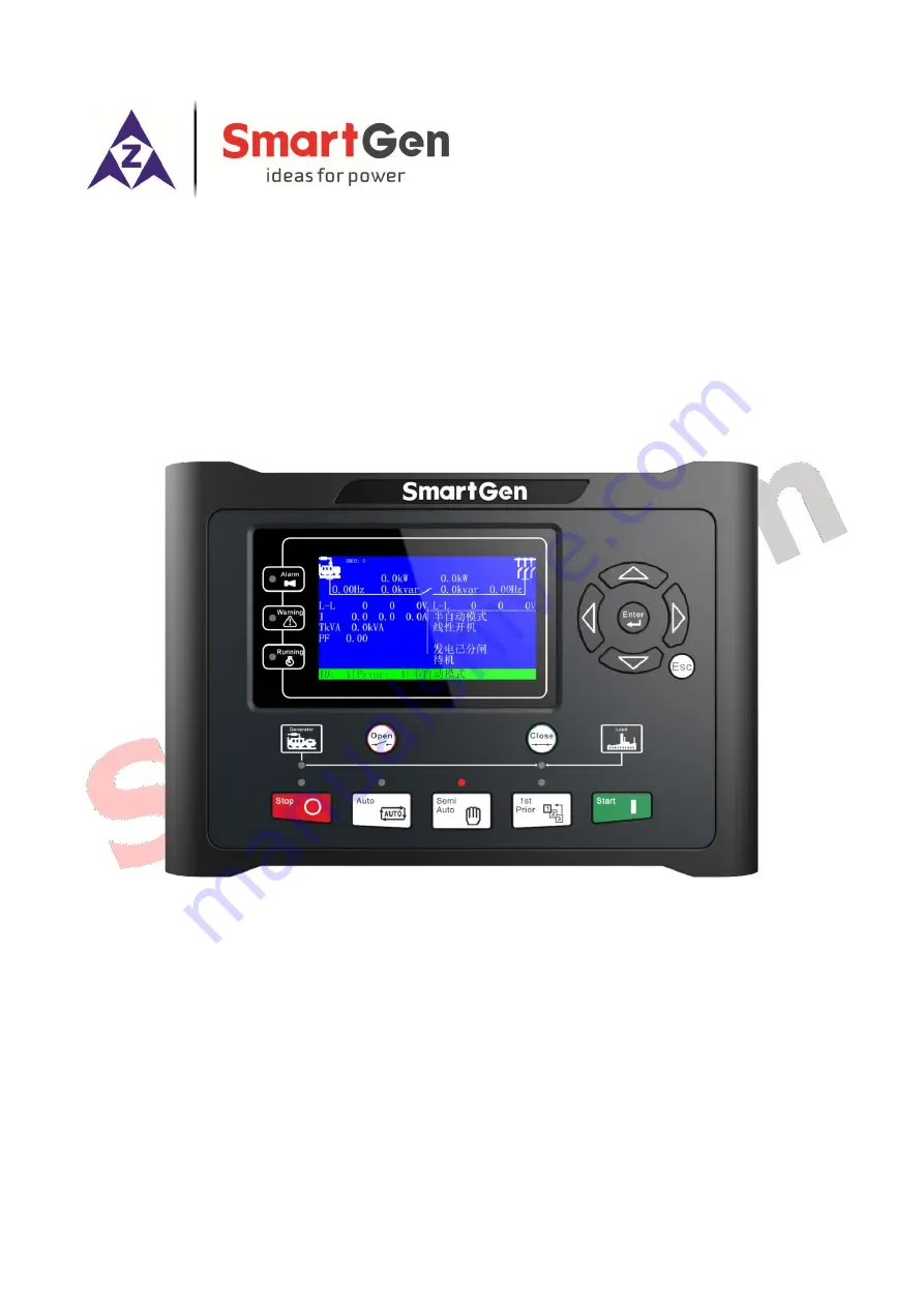
HMC6
POWER MANAGEMENT CONTROLLER
USER MANUAL
SMARTGEN (ZHENGZHOU) TECHNOLOGY CO.,LTD.
Страница 1: ...HMC6 POWER MANAGEMENT CONTROLLER USER MANUAL SMARTGEN ZHENGZHOU TECHNOLOGY CO LTD...
Страница 2: ...he right to change the contents of this document without prior notice Table 1 Version history Date Version Contents 2014 01 21 1 0 Original release 2018 06 02 2 0 Updated controller functions and deta...
Страница 3: ...l element of a procedure to ensure correctness CAUTION Indicates a procedure or practice which if not strictly observed could result in damage or destruction of equipment WARNING Indicates a procedure...
Страница 4: ...7 1 1 MANUAL MODE 18 7 1 2 SEMI AUTO MODE 18 7 13 AUTO MODE 19 7 2 WORKING MODE DESCRIPTION 20 8 PROTECTION 20 9 HARDWARE STRUCTURE 27 9 1 STRUCTURE DESCRIPTION 27 9 2 TERMINAL DESCRIPTION 27 9 2 1 SL...
Страница 5: ...42 10 6 4 OPEN BREAKER 43 10 6 5 HEAVY CONSUMER 44 10 6 6 LIGHT CONSUMER 45 11 SCOPES AND DEFINITIONS OF PROGRAMMABLE PARAMETERS 46 11 1 BUSBAR SETTING 46 11 2 TIMER SETTING 49 11 3 GENERATOR SETTING...
Страница 6: ...rs Light load the genset is still running if the load has fallen below the shutdown set value when the function is active Multiple speed adjusting output ports which including relay adjust speed outpu...
Страница 7: ...el generators Load sharing between diesel generators Fixed power for diesel generator asymmetrical load sharing Heavy consumer control fixed load NEL Non essential Load Trip Safety Mode reserve an add...
Страница 8: ...Safety stop safety trip Safety mode reserve an additional unit running on load Limit network connected gensets numbers Busbar breaking handle 4 SPECIFICATION Table 3 Specification Parameters Paramete...
Страница 9: ...C Protection Level IP65 when water proof gasket installed between control panel and enclosure Insulation Intensity Apply AC2 2kV voltage between high voltage terminal and low voltage terminal The lea...
Страница 10: ...priority and start the generator the earliest Close The unit will close the circuit breaker in Semi auto mode Open The unit will open the circuit breaker in Semi auto mode Up Increase 1 Screen scroll...
Страница 11: ...setting Timers setting Generator setting Generator load setting GB setting Digital inputs setting Relay outputs setting Module setting Synchronization setting Synchronous calibration Local module set...
Страница 12: ...art Delay Stop Delay Start Output Delay Stop Output Delay Start Wait Delay Stop Wait Delay Onload Stable Delay Transient Fault Delay Heavy Consumer Delay Alarm Start Delay Trigger Start Delay Form 3 U...
Страница 13: ...anual VOLT OUT do work in this mode 6 1 2 SEMI AUTO MODE Semi auto mode is activated by pressing key Semi auto means that the unit will not initiate any sequences automatically as is the case with the...
Страница 14: ...Stop a In breaker close status press open button in case of multi set operation first of all the system will transfer load and open breaker in case of single unit running it will open breaker directl...
Страница 15: ...ing status and the voltage frequency has not satisfy the on load requirement suddenly Transient Fault Delay will be initiated F V Fault latched alarm will be initiated if the on load requirement has n...
Страница 16: ...ion Manual Mode Start the gensets externally GOV input GOV output AVR input and AVR output are active monitor all generator parameters Trip and stop the gensets externally Semi auto Mode Start the gen...
Страница 17: ...Start the gensets according to the set priority and sequence The highest priority the minimum number will be started earliest following the second highest priority will be started E g the start seque...
Страница 18: ...umer connection will not be allowed Semi auto Start a Press the start button the controller firstly judges the feedback state of the shaft solenoid valve closing if configured If the state is not dete...
Страница 19: ...ter breaker opened or in breaker open status press stop button system will enter into Stop Output Delay while the stop relay will activate c After Stop Output Delay system will enter into Wait for Sto...
Страница 20: ...SG and DG When SG opens all loads will be transferred to DG side SG opens and stops Note When in SG mode outputs of GOV and AVR should be set as none if SG can not achive speed governing 8 PROTECTION...
Страница 21: ...nitiate a warning alarm Warn It is active after the switch has closed 5 Undervolt 2 When busbar voltage has fallen below than the set value 2 it will initiate a trip alarm Trip It is active after the...
Страница 22: ...t frequency has exceeded the set value 2 it will initiate a trip alarm Trip Always active 4 Overfreq 3 When genset frequency has exceeded the set value 3 it will initiate a trip alarm Trip Always acti...
Страница 23: ...ive after the genset has started 18 Freq Volt Fault Start the system if the voltage and frequency have not reached the requirements after the on load stable delay has expired it will initiate a block...
Страница 24: ...ower is positive has exceeded the Non Essential Load 2 Trip set value it will initiate a trip alarm Warn Non Essential Load 2 Trip It is active after the Non Essential Load switch 2 has closed 7 Non E...
Страница 25: ...expired it will initiate a trip alarm Lock It is active after the switch has opened 3 Abnormal Trip of Main Switch When the controller detects that the main switch abnormal trip input port is active t...
Страница 26: ...ctive 5 DIN1 Com Fail When the controller detects DIN1 module communication failure it will initiate a warning alarm Warn When DIN1 is enabled 6 DIN2 Com Fail When the controller detects DIN2 module c...
Страница 27: ...minals Slot Terminal Remarks Slot 1 1 6 Power supply reply output port Slot 2 7 15 Relay output port Slot 3 16 23 Relay output port Slot 4 24 35 CANBUS port GOV analog speed regulator port AVR analog...
Страница 28: ...ery directly instead of start battery or charging generator to ensure stable supply of HMC6 9 2 2 SLOT 2 SLOT 3 RELAY OUTPUT PORT Table 12 Slot 2 Slot 3 Relay Output Port Terminal Function Description...
Страница 29: ...simultaneously 20mA 20mA and 10V 10V Can be transducer AOUT2 output 34 VDC Output 10V 10V 35 COM6 AVR COM Output 9 2 4 SLOT 5 SLOT 6 SLOT 7 GENERATOR VOLTAGE INPUT BUSBAR VOLTAGE INPUT GENERATOR CURR...
Страница 30: ...PUT 5 Digital input port 5 60 AUX INPUT 6 Digital input port 6 61 COM 7 COM port of frequency input port and voltage input port 62 FREQ IN IN 7 External frequency active power adjust input Can be reus...
Страница 31: ...ion Port Terminal Function Description Remarks 68 B RS485 communication port Baud rate 9600bps Standard MODBUS protocol 69 A 70 SCR RS485 shield port Shielded wire single end earthed 9 3 CONNECTION 9...
Страница 32: ...gnal Table 18 FREQ IN and VOLT IN Function Description Function Description External Setpoint Trigger Bar Input Voltage FREQ IN External frequency adjust Single unit running or generator breaker is op...
Страница 33: ...Controller User Manual Page 33 of 87 0 10V input connection 62 63 61 10VDC 0VDC 2k 1 4W Fig 8 0 10V Input Connection Diagram 10V 10V input connection 62 63 61 10VDC 0VDC 2k 1 4W 10VDC Fig 9 10V 10V In...
Страница 34: ...NK PORT Data sharing and data communication functions among HMC6 controllers are implemented via MSC LINK CANBUS port Detailed connection way is as following Fig 10 HMC6 Module Communication Connectio...
Страница 35: ...ch unit can be selected as running with fixed power This can be done from the panel parameters or via a discrete input The unit selected for fixed power operation will automatically be set in SEMI AUT...
Страница 36: ...ization is reduce the phase angle between two systems refer to 3 phase systems of generator and busbar Voltage difference frequency difference and angle difference should be set during dynamic synchro...
Страница 37: ...enset started and in parallel then the acknowledged signal will be initiated 10 4 3 HEAVY CONSUMER PERMISSION If a heavy consumer is requested the system calculates the power needed according to the r...
Страница 38: ...vy load stability delay the controller starts to output the heavy load answer signal e During or after the output delay of heavy load answer the bus bar has different processing states for HC1 heavy l...
Страница 39: ...L The trip of Non Essential Load NEL groups is carried out in order to protect the busbar Each HMC6 controller is able to handle three non essential load trip NEL Trip priority is NEL1 NEL2 NEL3 If th...
Страница 40: ...Delay Meet with load conditions Breaker Close Start Active Y N End Wait for Start Delay Start Success Y Start Fail Alarm Delay Expired Load Stable Delay Y Frequency Volt Fault N Start Output Delay Nor...
Страница 41: ...87 10 6 2 STOP Start Stop Active Y N Ramp off Load Below Opening Load Y CB Open Delay End CB Open OK Open Fail Alarm N N Genset Stop Y Stop Output Delay Wait for Stop Delay Stop Success Y Stop Fail Al...
Страница 42: ...m End CB Close Success Y CB Close Fail Alarm Y N Y Satisfy CB Close Conditions N N Y Multi units CB Sync Close Load Sharing Mode Base Load Output Load Sharing Mode Output or Single Unit Running Y N Si...
Страница 43: ...ler User Manual Page 43 of 87 10 6 4 OPEN BREAKER Start CB Open or Stop Active Y N Ramp off Load Blew Opening Load Y CB Open Delay End CB Open Success Open Fail Alarm N N Stop Operation Y Fig 18 Syste...
Страница 44: ...6 5 HEAVY CONSUMER Start Satisfy HC Load Start Backup Gensets N Y End Heavy Consumer Active Busbar Power Calculation HC Stable Delay Schedule Start Stop HC Ack Output Satisfy HC Load N Y HC Feedback A...
Страница 45: ...ower Management Controller User Manual Page 45 of 87 10 6 6 LIGHT CONSUMER Start Load Below Stop Set Value End Light Consumer Active CB Open N Gensets Parallel Running Y Fig 20 Light Consumer Workflow...
Страница 46: ...ed Frequency 10 0 75 0 Hz 50 0 Standard for checking busbar over under frequency 3 Volt Trans PT Action 0 1 0 Disable 1 Enable 0 Disable Users can set the primary voltage and secondary voltage of the...
Страница 47: ...Set Action 0 1 0 Disable 1 Enable 0 Disable 27 Set value 50 100 70 28 Delay 0 1 100 0 s 2 0 29 Alarm Type 0 5 2 Trip 30 Over Frequency 1 Set Action 0 1 0 Disable 1 Enable 1 Enable Setting value is bus...
Страница 48: ...0 1 100 0 s 8 0 53 Alarm Type 0 5 2 Trip 54 ROCOF Set Action 0 1 0 Disable 1 Enable 0 Disable 55 Set value 0 1 00 Hz s 0 20 When the controller detects that the busbar ROCOF has exceeded the set value...
Страница 49: ...or Stop delay the genset is stopped successfully if the voltage and frequency are 0 while the warning alarm will be initiated if they are not 0 7 Wait For Stable 0 3600 s 5 Time from start signal is a...
Страница 50: ...3 wire 2P3W 3 1 phase 2 wire 1P2W 2 Rated Voltage 30 30000 V 230 To offer standards for detecting of generator s over under voltage It is primary voltage when using voltage transformer it is line vol...
Страница 51: ...ated voltage Delay value and return value can be set 12 Set value 80 120 105 13 Delay 0 1 100 0 s 5 0 14 Alarm Type 0 5 0 Block 1 Warn 2 Trip 3 Shutdown 4 Safety Trip 5 Safety Stop 1 Warn 15 Over Volt...
Страница 52: ...0 s 5 0 34 Alarm Type 0 5 1 Warn 35 Over Frequency 2 Set Action 0 1 0 Disable 1 Enable 1 Enable 36 Set value 80 120 107 37 Delay 0 1 100 0 s 3 0 38 Alarm Type 0 5 2 Trip 39 Over Frequency 3 Set Action...
Страница 53: ...1 62 Alarm Type 0 5 1 Warn 63 Adjust Frequency Input Set Adjust Frequency 0 100 10 This function can be used when power mode is fixed and external adjust input is active Adjust frequency before breake...
Страница 54: ...7 Overload To Ask 2 0 2000 kW 100 The request active power of busbar overload 8 Overload Rated 2 0 2000 kW 60 The rated active power of busbar overload 9 Overload To Ask 3 0 2000 kW 100 The request a...
Страница 55: ...ction Action 0 1 0 Disable 1 Enable 1 Enable 36 Set Value 0 200 8 37 Delay 0 1 999 9 s 5 0 38 Alarm Type 0 5 1 Warn 39 Reverse Power 2 Protection Action 0 1 0 Disable 1 Enable 1 Enable 40 Set Value 0...
Страница 56: ...EL 2 trip is active when current of any busbar genset has exceeded the set value 64 Set Value 50 200 100 65 Delay 0 1 999 9 s 8 0 66 NEL 3 Current Trip Action 0 1 0 Disable 1 Enable 1 Enable External...
Страница 57: ...ime 0 20 0 s 5 0 Pulse width of switch off When it is 0 means output constantly 3 Switch Failure Action 0 5 0 Lock Action when switch closing and opening feedback is inconsistent with switch state 4 C...
Страница 58: ...Enabled 0 1 0 Disable 1 Enable 0 Disable Connect with extension module DIN16 1 when input ports of HMC6 are not enough If still not enough the external DIN16 2 is extended 10 Alarm Delay 0 1 999 9 s...
Страница 59: ...hosen 23 HMP300 Enable 0 1 0 Disable 24 0 1 999 9 s 5 0 Alarm delay 25 Self check Abnormal Return to Manual 0 1 0 Disable It forces the controller into manual mode if the self check is abnormal 26 Eng...
Страница 60: ...Voltage 2 Busbar Frequency 3 Busbar Active Power 4 Busbar Inactive Power 5 Busbar Apparent Power 6 Reserved 7 Gen Voltage 8 Gen Frequency 9 Gen Active Power 10 Gen Inactive Power 11 Gen Apparent Power...
Страница 61: ...used 10 Active Type 0 1 0 0 Close activate 1 Open activate Programmable Input 2 11 Contents Setting 0 99 0 Not used 12 Active Type 0 1 0 0 Close activate 1 Open activate Programmable Input 3 13 Conte...
Страница 62: ...OV output drop speed signal when the input is active 4 Volt Raise Raise voltage relay is active and AVR output raise voltage signal when the input is active 5 Volt Drop Drop Voltage relay is active an...
Страница 63: ...or when the external adjust input is active the active power and the reactive power can be adjusted via external FREQ IN port and VOLT IN port 20 Cycle Start Cycle start mode is carried out when the i...
Страница 64: ...Start Input If it failed to start this input is active and will issues start signal again 40 System Manual Mode Input When input is active all gensets on the busbar become manual mode 41 System Semi a...
Страница 65: ...e input port is active 57 Forced Auto Mode 58 Reserved Reserved 59 SG Enabled If module is not set as SG mode the controller will work in SG mode when input port is effective 60 SG DG Switching When i...
Страница 66: ...ixed Fixed Speed Raise 2 Active Type 0 1 0 0 Open 1 Close Output 2 3 Contents Setting Fixed Fixed Speed Drop 4 Active Type 0 1 0 0 Open 1 Close Aux output 7 5 Contents Setting 0 150 3 Volt Raise 6 Act...
Страница 67: ...aise Active when the generator is raising speed 2 Speed Drop Active when the generator is dropping speed 3 Volt Raise Active when the generator is raising voltage 4 Volt Drop Active when the generator...
Страница 68: ...tive when the generator over voltage 1 alarm occurs 30 Gen Over Voltage 2 Active when the generator over voltage 2 alarm occurs 31 Gen Under Frequency 1 Active when the generator under frequency 1 ala...
Страница 69: ...55 Over Current 1 Active when generator over current 1 occurs 56 Over Current 2 Active when generator over current 2 occurs 57 Over Current 3 Active when generator over current 3 occurs 58 Over Curre...
Страница 70: ...Flag 5 86 PLC Flag 6 87 PLC Flag 7 88 PLC Flag 8 89 PLC Flag 9 90 PLC Flag 10 91 PLC Flag 11 92 PLC Flag 12 93 PLC Flag 13 94 PLC Flag 14 95 PLC Flag 15 96 PLC Flag 16 97 PLC Flag 17 98 PLC Flag 18 9...
Страница 71: ...oad receiving mode if SG on load is effective but SG outputs when capacity is insufficient to receive the full load 124 DG Capacity Insufficient When the controller operates in SG mode and load receiv...
Страница 72: ...se it will not output 11 9 SYNCHRONIZATION SETTING Table 30 Synchronization Settings No Items Parameter Range Default Description Synchronization Setting Basic 1 Governor Output 0 2 1 0 Internal relay...
Страница 73: ...cy trip and stop and over current and the faulty units must be switched off after the other normal units are switched on 18 Uninterrupted Power Supply 0 1 0 0 Disable 1 Enable In auto mode enable Unin...
Страница 74: ...start other units 26 Calling for Less Sets 0 100 20 Loading percentage of busbar that scheduled to stop other units 27 Calling for Start Power 0 20000 kW 50 Power left of busbar that scheduled to star...
Страница 75: ...hen the initial phase difference between generator and bus is lower than Sync Phase Angle Difference 40 Fail to Sync Delay 5 0 300 0 s 60 0 When there is no sync signal been detected during Fail to Sy...
Страница 76: ...internal analog voltage is adjusted to control the engine speed before parallel connection Stability 0 2000 20 Relay Control Response 0 1 4 00 Hz s 1 20 The internal relay is adjusted to control the...
Страница 77: ...n time of SG and DG 16 Fixed Min On load 0 100 0 0 0 When the controller works in both SG mode and fixed power mode if the total load is lower than the active power of fixed output of SG the maximum p...
Страница 78: ...ocal Parameter Settings No Items Parameter Range Default Description Local Setting 1 Local Modules Type 0 5 0 0 None 1 HMC6000S 2 HMC6000E 3 HMC6000A 4 HMC6000ED 5 HMC6000EG 11 12 DIN16 SETTING HMC6 c...
Страница 79: ...e Input Port 10 19 Contents Setting 0 99 0 Not used 20 Active Type 0 1 0 0 close activate 1 open activate Input Port 11 21 Contents Setting 0 99 0 Not used 22 Active Type 0 1 0 0 close activate 1 open...
Страница 80: ...Setting 0 150 0 Not Used 8 Active Type 0 1 0 0 open 1 close Output Port 5 9 Contents Setting 0 150 0 Not Used 10 Active Type 0 1 0 0 open 1 close Output Port 6 11 Contents Setting 0 150 0 Not Used 12...
Страница 81: ...0 1 0 0 open 1 close Output Port 14 27 Contents Setting 0 150 0 Not Used 28 Active Type 0 1 0 0 open 1 close Output Port 15 29 Contents Setting 0 150 0 Not Used 30 Active Type 0 1 0 0 open 1 close Ou...
Страница 82: ...LED Color 0 2 0 0 Red 1 Green 2 Yellow Output 4 10 Contents Setting 0 150 0 Not used 11 Active Type 0 1 0 0 open 1 close 12 LED Color 0 2 0 0 Red 1 Green 2 Yellow Output 5 13 Contents Setting 0 150 0...
Страница 83: ...Setting 0 150 0 Not used 41 Active Type 0 1 0 0 open 1 close 42 LED Color 0 2 0 0 Red 1 Green 2 Yellow Output 15 43 Contents Setting 0 150 0 Not used 44 Active Type 0 1 0 0 open 1 close 45 LED Color 0...
Страница 84: ...505 User defined 2Bytes 3506 User defined 2Bytes 3507 User defined 2Bytes 3508 User defined 2Bytes 3509 User defined 2Bytes 3510 User defined 2Bytes 3511 User defined 2Bytes 3512 User defined 2Bytes 3...
Страница 85: ...e is no high circumfluence on HMC6 current screen c During parallel operation off load check if the output of active and reactive power is equal to zero if it is not then check if there is power oscil...
Страница 86: ...ctive Range 10V 10V 3 Output And Expand Relays NOTE All outputs of controller are voltage free output rated capacity is 8A If need to expand the relays please add freewheel diode to both ends of expan...
Страница 87: ...controlling parameters Debug every single unit based on the commissioning process Paralleling units cannot raise power or drop power or just can little raise drop power When the internal analog speed...