background image

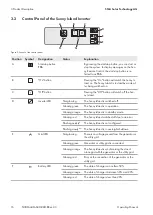
Position

Symbol

Designation

Explanation

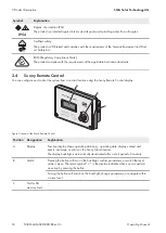
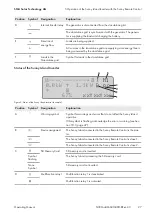
D

Internal transfer relay The generator is disconnected from the stand-alone grid.

The stand-alone grid is synchronized with the generator. The genera-
tor is supplying the loads and charging the battery.

E

Direction of
energy flow

Loads are being supplied.

AC sources in the stand-alone grid are supplying more energy than is
being consumed by the stand-alone grid.

F

Loads in the
Stand-alone grid

Symbol for loads in the stand-alone grid

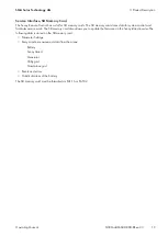
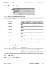
Status of the Sunny Island Inverter

0.0kW    1.1kW

*

67%

oo

xx:xx:xx

--- -------

! M1

B

A

C

D

E

F

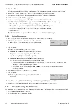
Figure 8: Status of the Sunny Island inverter (example)

Position

Symbol

Designation

Explanation

A

Warning symbol

Symbol for warnings and errors that do not affect the Sunny Island
operation.

If this symbol is flashing, acknowledge the error or warning (see Sec-
tion 10.3, page 47)
.

B

Device assignment

The Sunny Island connected to the Sunny Remote Control is the mas-
ter.

The Sunny Island connected to the Sunny Remote Control is slave 1.

The Sunny Island connected to the Sunny Remote Control is slave 2.

C

SD Memory Card

SD memory card is inserted.

Symbol
flashing

The Sunny Island is accessing the SD memory card.

None
Symbol

SD memory card not inserted.

D

Multifunction relay 1

Multifunction relay 1 is deactivated.

Multifunction relay 1 is activated.

5 Operation of the Sunny Island Inverter with the Sunny Remote Control

SMA Solar Technology AG

Operating Manual

27

SI30M-44M-60H-80H-BE-en-33

Содержание SUNNY ISLAND 3.0M

Страница 1: ...SUNNY REMOTE CONTROL Warning Load Memory Card Grid Generator Operating Manual SUNNY ISLAND 3 0M 4 4M 6 0H 8 0H SUNNY REMOTE CONTROL SI30M 44M 60H 80H BE en 33 Version 3 3 ENGLISH...

Страница 2: ...explicitly identified as such Missing designations do not mean that a product or brand is not a registered trademark Modbus is a registered trademark of Schneider Electric and is licensed by the Modb...

Страница 3: ...2 Standard Mode 24 5 2 1 Display of Operating States 24 5 2 2 Information Page in Systems for Increased Self Consumption and Battery Backup Systems 25 5 2 3 Information Page in Off Grid Systems 26 5...

Страница 4: ...Fault Conditions 47 10 3 Acknowledge Errors 47 10 4 Logged Events 48 10 4 1 Sunny Island Category 1xx 48 10 4 2 Battery Category 2xx 48 10 4 3 Generator Category 4xx 49 10 4 4 Utility Grid Category 5...

Страница 5: ...y 106 13 1 8 Grid Feed Category 106 13 1 9 Loads Category 106 13 1 10 PV System Category 107 13 1 11 System Category 107 13 1 12 Time Category 107 13 1 13 Identity Category 108 13 1 14 Password Catego...

Страница 6: ...13 2 5 4 MMC Card 550 157 13 2 5 5 Grid 560 157 14 Parameters in the Communication Product 158 15 Menu Structure 159 15 1 User Mode 159 15 2 Installer Mode and Expert Mode 160 16 Contact 161 Table of...

Страница 7: ...on how to secure a system against unintentional reactivation Training on the maintenance and cleaning of the Sunny Island inverter Knowledge of and compliance with this document and all safety inform...

Страница 8: ...Several elements that are to be selected Select 600 Direct Access Select Number Button Key Button that is to be selected or clicked on Select Enter 1 5 Nomenclature Complete designation Designation i...

Страница 9: ...presented as follows menu number period parameter number and parameter name e g 150 01 GdRmgTm The term parameter includes parameters with configurable values as well as parameters for displaying val...

Страница 10: ...n of SMA Solar Technology AG Unauthorized alterations will void guarantee and warranty claims and in most cases terminate the operating license SMA Solar Technology AG shall not be held liable for any...

Страница 11: ...t live components Danger to life from electric shock due to damaged inverter Operating a damaged inverter can lead to hazardous situations that can result in death or serious injuries due to electric...

Страница 12: ...the battery and cause an explosion This can result in death or serious injury Protect the battery environment from open flames embers and sparks Install operate and maintain the battery in accordance...

Страница 13: ...er battery connection may result in excessively high transition resistances Excessive transition resistances give rise to localized heat build up Ensure that all pole connectors are connected with the...

Страница 14: ...f FLA batteries In the case of lead acid batteries measure and log the voltages of the individual cells Perform and log the test routines required by the battery manufacturer Prior damage to batteries...

Страница 15: ...crease the availability of the off grid system and reduce the battery capacity the Sunny Island can use and control a generator as an energy reserve The loads may temporarily overload the Sunny Island...

Страница 16: ...is in operation Glowing orange The Sunny Island is in standby mode Glowing red The Sunny Island switched off due to an error Flashing quickly The Sunny Island is not configured Flashing slowly The Su...

Страница 17: ...tion Danger to life due to electric shock The product operates at high voltages All work on the product must be carried out by qualified persons only Risk of burns due to hot surfaces The product can...

Страница 18: ...rd Grid Generator A B C Figure 3 Layout of the Sunny Remote Control Position Designation Explanation A Display Four line display shows operating data e g operating state display values and events warn...

Страница 19: ...firmware on the Sunny Island inverter The following data is stored on the SD memory card Parameter Settings Every minute measurement data from the areas Battery Sunny Island Generator Utility grid St...

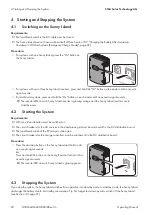
Страница 20: ...equirements All Sunny Island inverters must be switched on The circuit breakers for the AC sources in the stand alone grid must be switched off in the AC distribution board The load break switch of th...

Страница 21: ...Emergency Disconnection of the System Effects of an emergency disconnection Emergency disconnection triggers the uncontrolled shutdown of the system and unsaved data is lost Only use the emergency dis...

Страница 22: ...nny Remote Control switches to the Inverter setting page 3 Set the time controlled inverter operation Select the Start date for time controlled inverter operation Start Date parameter and set it to th...

Страница 23: ...aller Display of and access to configuration and operation parameters The installer mode is protected with an installer password In display messages on the Sunny Remote Control Installer refers to the...

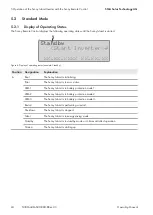
Страница 24: ...us LBM 1 The Sunny Island is in battery protection mode 1 LBM 2 The Sunny Island is in battery protection mode 2 LBM 3 The Sunny Island is in battery protection mode 3 Restart The Sunny Island is perf...

Страница 25: ...unny Remote Control is the mas ter The Sunny Island connected to the Sunny Remote Control is slave 1 The Sunny Island connected to the Sunny Remote Control is slave 2 C SD Memory Card SD memory card i...

Страница 26: ...inverter example Position Designation A Graphical Representation of the Energy Flows B Status of the stand alone grid C Status of the Sunny Island Inverter D State of charge of the battery E Status o...

Страница 27: ...bol Designation Explanation A Warning symbol Symbol for warnings and errors that do not affect the Sunny Island operation If this symbol is flashing acknowledge the error or warning see Sec tion 10 3...

Страница 28: ...tate of charge 0 0kW 1 1kW oo 67 xx xx xx M1 B A Figure 9 State of charge of the battery in standard mode example Position Designation Explanation A Battery Battery symbol B State of charge State of c...

Страница 29: ...rator via Sunny Remote Con trol or a generator was requested via the DigIn input Time You have started the generator for one hour via Sunny Re mote Control B Power of the generator or the utility grid...

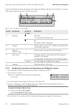
Страница 30: ...etting pages are available for this category E Parameter Parameters with the current values 5 3 2 Displaying Parameters and Operating and Setting the System 1 Press the button to activate the display...

Страница 31: ...bol appears next to the parameter Repetition The Sunny Remote Control switches from setting page Inverter 1 2 to setting page Inverter 2 2 Press the button Turn the button to the right until Weekly ap...

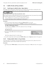
Страница 32: ...checksum of the operating hours Runtime This determines the installer password Example Calculating the checksum The operating hours Runtime are 1234 h The checksum is the sum of all digits 1 2 3 4 10...

Страница 33: ...nstaller mode example Position Designation Explanation A Menu number and parameter number B Menu path The two previously selected menu levels C Return symbol Return symbol for setting the parameter If...

Страница 34: ...button The return symbol is flashing next to the value Stop device to change the value appears in the display The parameter can be changed only in standby mode Stop the system see Section 4 3 page 20...

Страница 35: ...on the Sunny Remote Control see Section 5 4 1 page 32 2 Select the parameter 600 02 Select Number and set the five digit number The parameter is displayed The display shows Item not Found You are sti...

Страница 36: ...g the reason for the generator request sent by the Sunny Island is displayed on the screen of the Sunny Remote Control as parameter number and parameter name 133 01 GnDmdSrc The same information appea...

Страница 37: ...rameter set saves all settings This makes it possible to test the settings of a new parameter set without having to delete the old parameter set Useful hint As soon as you have adjusted the system to...

Страница 38: ...see Section 13 2 3 1 Inverter 310 page 149 Procedure 1 Switch to installer mode on the Sunny Remote Control see Section 5 4 1 page 32 2 Select the parameter 312 11 CardStt and read off the value 7 2 5...

Страница 39: ...re batstat txt Statistical values of the battery These values are saved every night at 10 00 p m batstat sma Statistical values of the battery for evaluation by SMA Solar Technology AG sim ccf System...

Страница 40: ...ration Control Unit Main processor Digital signal processor Logic component SMA Speedwire data module for Sunny Island Protocol converter The version number of the software package is based on the fir...

Страница 41: ...4 1 page 32 3 Set the parameter 250 32 UpdMode to Auto 4 Set the parameter 250 33 UpdAutoTime to the desired firmware update time 5 Transfer the firmware update from the computer to the Sunny Island...

Страница 42: ...er 250 33 UpdAutoTime to the desired firmware update time 5 Activate the automatic software update in the Sunny Home Manager see user manual of the Sunny Home Manager Once the transfer to the SD memor...

Страница 43: ...equipment Carry out work on the generator in accordance with the manufacturer s specifications Requirements The Sunny Island must be able to control the generator via a control cable The Sunny Remote...

Страница 44: ...he stand alone grid from the generator 2 Open the load break switch between the generator and the Sunny Island 3 Stop the generator see manufacturer s manual The generator is stopped After the power d...

Страница 45: ...n damage or destroy the Sunny Island Ground yourself before touching any component 6 Loosen all screws of the enclosure lid and remove the enclosure lid 7 Ensure that the DC connection is disconnected...

Страница 46: ...use the same number range 1xx Sunny Island 2xx Battery 3xx Generator or utility grid 4xx Generator 5xx Utility grid 6xx Relay 7xx System 8xx External devices and components 9xx General Meaning of abbr...

Страница 47: ...tory Errors that are still pending are entered again after activation Errors that were detected by the Sunny Island before activation and are no longer detected after activation are shown in the list...

Страница 48: ...External stop E133 SlfCsmpStart Start of increased self consumption E134 SlfCsmpStop Stop of increased self consumption E135 SlfCsmpChrgOnly The battery is charged only when increased self consumptio...

Страница 49: ...lled generator operation started E408 GnCurCtlStp Current controlled generator operation stopped 10 4 4 Utility Grid Category 5xx No Name Description E501 GdSocOn Grid request due to low battery state...

Страница 50: ...22 Rly2Slv2On Multifunction relay 2 of slave 2 is activated E625 DigInOff No voltage at input DigIn Low E626 DigInOn Voltage at input DigIn High 10 4 6 System Category 7xx No Name Description E705 Pwr...

Страница 51: ...External Events 9xx No Name Description E901 BMSStrSOCRecal SOC recalibration started E902 BMSStpSOCRecal SOC recalibration stopped E903 BMSStrPwrLim Active power limitation started derating E904 BMS...

Страница 52: ...in the transformer of the device at L3 Temperature of the trans former in slave 2 is too high due to overload or ambient tempera ture F 113 InvTmpHi 3 Overtemperature in the in verter bridge of the d...

Страница 53: ...sure that the Sunny Island is functional For this disconnect all AC sources and loads from the Sunny Island and restart the Sunny Island Find the cause of the overvoltage through measurement and step...

Страница 54: ...e power by replacing the Sunny Island with a higher powered version or by installing additional Sunny Island inverters W 138 DerateSlv1 1 Derating due to tempera ture L2 slave 1 has reduced the batter...

Страница 55: ...1 has measured an undesired voltage at connection AC1 W 160 VtgOnAC1DetSlv2 1 Voltage at AC connection Line conductor L3 slave 2 has measured an undesired voltage at connection AC1 F 162 OvrCurDet 2 T...

Страница 56: ...t L3 slave 2 has been loaded over its rated short term capacity F 175 StopSlvError 1 slave is in Fault mode The clus ter is stopped Contact the Service see Section 16 Contact page 161 F 176 CurTrfSns...

Страница 57: ...the multicluster system At line conductor L3 an anti islanding error occurs due to the open pre fuse 10 5 2 Battery Category 2xx No Name Level Cause Corrective measures F 201 VBATMAX 2 Measuring range...

Страница 58: ...arn 1 Battery overvoltage Battery voltage is temporarily too high W 211 BatTmpLoWarn 1 Undertemperature fault in battery The battery tempera ture is too low Ensure that the battery room is sufficientl...

Страница 59: ...inverters are set to stand alone grid operation see the installation manuals of the SMA inverters W 310 RlyProtectSlv1 1 Excessive current has been applied to the transfer relay of the device at L2 E...

Страница 60: ...L3 The voltage of the generator or the utility grid at slave 2 is too low W 319 ExtVtgHi 1 Disconnection from the ex ternal grid due to overvolt age at line conductor L1 The voltage of the generator...

Страница 61: ...he frequency of the generator or the utility grid at slave 2 is too low W 327 ExtFrqHi 1 Disconnection from the ex ternal grid due to too high frequency at line conduc tor L1 The frequency of the gene...

Страница 62: ...ductor L3 Undesired stand alone grid is present at connec tion AC2 of slave 2 W 335 ExtVtgRdtErr 1 Disconnection from external source due to exceeding the configured thresholds in the device at L1 Th...

Страница 63: ...tion AC2 is too high or the battery volt age too low Contact the Service if required see Section 16 Contact page 161 W 344 AcVtglimSlv1 1 Disconnection from the ex ternal grid due to insufficient batt...

Страница 64: ...rid due to line conductor failure over load at connection AC2 W 351 ExtScirDet 1 Disconnection from the ex ternal grid due to external short circuit at line conduc tor L1 Short circuit is present at c...

Страница 65: ...ed to the same line conductor F 366 HotAcBus 3 When the tie switch is open AC voltage is present at line con ductor L1 Master Ensure that the triggering of the tie switch is correct Ensure that the ti...

Страница 66: ...parame ter value 232 04 GdCurNom or 234 03 GnCurNom by 2 Reduce power consumption of all loads Reduce power output of the AC sources e g PV inverter W 378 ExCurExcSlv1 1 The external current measured...

Страница 67: ...e g for PV inverters preferably request the generator at night If the generator can absorb reverse power adjust the settings for reverse power see the Sunny Island inverter installation manual W 402...

Страница 68: ...he feed in current is greater than the set maximum value 232 04 GdCurNom 10 5 6 Relay Category 6xx No Name Level Cause Corrective measures F 605 TransfNotOpn 4 Transfer relay does not open at line con...

Страница 69: ...he watch dog of the operation control unit has tripped Contact the Service if required see Section 16 Contact page 161 W 715 MMCUpdFail 1 The update cannot be carried out The type or format of the SD...

Страница 70: ...errors and eliminate the causes Ensure that the parameter 250 01 AutoStr is set to 3 W 725 AutoStrCntSlv2 1 Autostart meter elapsed in the device at L3 Maximum number of autostarts for slave 2 has bee...

Страница 71: ...Section 16 Contact page 161 Ensure that the terminators in the communication bus are attached Ensure that undamaged CAT5e cables are used for communication and that the cables are plugged in correctl...

Страница 72: ...circuit breakers of the Sunny Island inverters in the Multicluster Box are closed Ensure that the cabling at connection AC1 is correctly installed W 759 McNoVtgSv1 1 Voltage of the main cluster can no...

Страница 73: ...essor in the device at L2 slave 1 has been identified Contact the Service see Section 16 Contact page 161 W 792 RsDspSlv2 1 Reset of the signal processor in the device at L3 slave 2 has been identifie...

Страница 74: ...ction 16 Contact page 161 W 807 BoxGdVtg 1 Voltage of the external energy source is not within the valid thresholds for connection Acknowledge the error see Section 10 3 page 47 Contact the Service se...

Страница 75: ...correctly Exception Load shedding con tactor Q109 in the Multicluster Box 12 MC BOX 12 3 20 is not functioning correctly F 818 BoxPhsFail 4 Box phase missing One line conductor of a Sunny Island in v...

Страница 76: ...Contactor Q10 does not open Exception Load shedding con tactor Q110 in the Multicluster Box 12 MC BOX 12 3 20 does not open Contact the Service see Section 16 Contact page 161 F 835 BoxQ10NotClose 4...

Страница 77: ...talled Ensure that the current firmware version of the SMA Speedwire data module is installed W 851 Sic1BatShort 1 Battery reversely connected or short circuit on PV charge controller 1 Connection of...

Страница 78: ...856 Sic1TmpHI 1 PV charge controller 1 de vice overtemperature Sun ny Island Charger 1 reports bat tery overtemperature W 857 Sic1ComLoss 1 No communication with DC charger for more than 24 h PV char...

Страница 79: ...ction 16 Contact page 161 W 865 Sic2TmpLo 1 Sensor error or undertem perature for the PV charge controller 2 charger temper ature Sunny Island Charger 2 reports battery undertempera ture Set the Sunny...

Страница 80: ...the system This will ensure that the PV array is not short circuited 3 Reset the system For this switch off the system wait ten minutes and restart W 873 Sic3PvVtgHi 1 PV charge controller 3 PV gener...

Страница 81: ...and Charger charge controller Disconnect the PV array from the Sunny Island Charger and restart the system This will ensure that the PV array is not short circuited W 882 Sic4BatVtgHi 1 PV charge cont...

Страница 82: ...d in the Sunny Island W 890 BoxMeas 2 Voltage or current measurement interferences at external mea surement point of the AC sub distribution Multicluster Box at line conductor L1 Master Ensure that th...

Страница 83: ...parameter 232 01 Country W 915 Timeout 1 Watchdog OCU An error has occurred in the program run se quence Contact the Service see Section 16 page 161 F 920 XA01General 3 Error message via SiCom Gen era...

Страница 84: ...ng the error cause in the external battery management system see battery manufacturer s documentation F 933 XA14PackBal 3 Error message via SiCom Re served Eliminating the error cause in the external...

Страница 85: ...tation W 947 XW12Bms 1 Warning via SiCom internal er ror in battery management Eliminating the error cause in the external battery management system see battery manufacturer s documentation W 948 XW13...

Страница 86: ...irradiation for PV inverters switch the Sunny Island on AC sources in the stand alone grid can start feeding in electric current only once the Sunny Island has been started and is in operation 10 6 2...

Страница 87: ...discharging even though the generator is running The Sunny Island may not have connected to the generator Eliminate the cause see Section 10 6 4 Questions Regarding the Generator page 87 The power of...

Страница 88: ...erator after disconnection from the generator due to non compliance with the thresholds for voltage and frequency why The Sunny Island is switched with a hysteresis i e the thresholds for connection d...

Страница 89: ...rformed in accordance with the specifications of the battery manufacturer see manual of the lithium ion battery Only run the emergency charge mode with Sunny Island after approval by the battery manuf...

Страница 90: ...atFuse and close the BatFuse see BatFuse installation manual 4 Start the generator 5 Switch the Sunny Island on see Section 4 1 page 20 6 If the Sunny Remote Control displays Init System press and hol...

Страница 91: ...ess using the QCG Only the address is changed all other configurations remain as they were e g assignment of the clusters in a multicluster system When replacing a master you must reconfigure the clus...

Страница 92: ...ify slave2 press Tss on the Slv 10 Press the start stop button on slave 2 An acoustic signal sounds and the QCG configures slave 2 11 Press the button on the Sunny Remote Control This closes the QCG T...

Страница 93: ...mode Procedure 1 Select the Battery display page on the Sunny Remote Control and press the button see Section 5 3 2 Displaying Parameters and Operating and Setting the System page 30 2 Select the para...

Страница 94: ...in blindness or serious chemical burns Protect the battery enclosure against destruction Do not open or deform the battery Do not throw batteries into fire Batteries may explode in fire Whenever work...

Страница 95: ...dure Clean the ventilation grids Clean the fans Cleaning the Ventilation Grids Proceed as follows to clean each ventilation grid Procedure 1 Remove the ventilation grid laterally 2 Damage to the inver...

Страница 96: ...Clean the fan guard with a soft brush a paint brush a cloth or compressed air 4 Check whether the fan is soiled If the fan is soiled remove the fan Use a screwdriver to push the two locking tabs at t...

Страница 97: ...metal parts on the battery Danger to life due to incompatible lithium ion battery An incompatible lithium ion battery can lead to a fire or an explosion With incompatible lithium ion batteries it is n...

Страница 98: ...vior of the Sunny Island inverter see technical information List of Approved Lithium Ion Batteries Set the battery capacity for a ten hour electric discharge C10 The battery manufacturer specifies the...

Страница 99: ...parameter BatCpyNom set the C10 capacity of the battery see the Sunny Island inverter installation manual for how to calculate the battery capacity and confirm the battery capacity with Y 13 Make the...

Страница 100: ...s see Section 9 page 45 1 Ensure that the Sunny Island is disconnected from all voltage sources see Section 9 page 45 2 Remove all cables from the Sunny Island 3 Close the Sunny Island 4 Remove the ve...

Страница 101: ...izontal position when moving it With the SI6 0H 11 and SI8 0H 11 remove the Sunny Island vertically upwards from the wall mounting bracket For this use the side recess grips or a steel rod diameter ma...

Страница 102: ...the Sunny Island inverter Yes Initiate restart No Do not initiate restart Str Date Start date for time controlled operation of the Sun ny Island in dd mm yy In time controlled operation the Sunny Isla...

Страница 103: ...rrent charging process Boost Boost charge is enabled Full Full charge is enabled Float Float charge is enabled Equalize Equalization charge is en abled Silent The Sunny Island has switched to energy s...

Страница 104: ...Source for generator request None Generator has not been re quested Bat Electricity generator was re quested due to state of charge Lod Electricity generator was re quested due to load Tim Generator...

Страница 105: ...Explanation Mode Manual connection to the util ity grid Auto Enables automatic connection to the utility grid Stop Disconnects the Sunny Island from the utility grid Start Connects the Sunny Island t...

Страница 106: ...Power Power drawn from the utility grid in kW Energy Energy drawn from the utility grid in kWh 13 1 8 Grid Feed Category Display Pages The Sunny Remote Control displays these pages in a system for in...

Страница 107: ...Island inverters 3Phase Three phase system Box Type Type of connected Multicluster Box This parameter is shown only in multiclus ter systems MC Box 6 Multicluster Box 6 MC Box 12 Multicluster Box 12 M...

Страница 108: ...Directory of the Parameters in Installer Mode and Expert Mode 13 2 1 Display Values 13 2 1 1 Inverter 110 111 Total No Name Description 111 01 TotInvPwrAt Total active power of Sunny Island inverters...

Страница 109: ...f the Sunny Island inverter in Hz 112 06 InvPwrRt Reactive power of the Sunny Island inverter at line conductor L1 in kVAr expert mode 112 07 Rly1Stt Multifunction relay status 1 Off Multifunction rel...

Страница 110: ...slave 1 at line conductor L2 in A 113 05 InvPwrRtSlv1 Reactive power of slave 1 at line conductor L2 in kVAr expert mode 113 06 Rly1SttSlv1 Multifunction relay status 1 of slave 1 Off Multifunction r...

Страница 111: ...lave 2 at line con ductor L3 in A 114 05 InvPwrRtSlv2 Reactive power of slave 2 at line conductor L3 in kVAr expert mode 114 06 Rly1SttSlv2 Multifunction relay status 1 of slave 2 Off Multifunction re...

Страница 112: ...t 6 8 Energy saving mode ac tive 120 06 TotBatCur Total battery current of the cluster in A 120 07 BatTmp Battery temperature in C 120 08 RmgTmFul Remaining time until next full charge in days 120 09...

Страница 113: ...the external grid connection in kW 131 02 TotExtCur Total current of the external grid connection in A 131 03 TotExtPwrRt Total reactive power of the external grid connection in kvar 13 Parameters in...

Страница 114: ...utility grid Feed 6 Grid operation with feed back Grid feed in into the utility grid is possible Silent 7 Energy saving in the utility grid the Sunny Island is in energy saving mode SiStr 8 The Sunny...

Страница 115: ...Connecting Run 6 Operation Retry 7 Restarting Disconnect 8 Split Cool 9 Cooling down Lock 10 Locked after operation Fail 11 Error FailLock 12 Locked after error Reinit 13 Re detection of the generator...

Страница 116: ...AtSlv2 Total active power of the external grid connection at slave 2 line conduc tor L3 in kW 136 02 ExtVtgSlv2 Voltage of the external grid connection at slave 2 line conductor L3 in V 136 03 ExtCurS...

Страница 117: ...arge controller 2 in kWh 143 03 Sic2PvPwr PV power of Sunny Island Charger charge controller 2 in W 143 04 Sic2PvVtg PV voltage of Sunny Island Charger charge controller 2 in V 143 05 Sic2BatVtg Batte...

Страница 118: ...ic4BatCur Battery current of Sunny Island Charger charge controller 4 in A expert mode 145 07 Sic4HsTmp Heat sink temperature of Sunny Island Charger charge controller 4 in C expert mode 13 2 1 5 Comp...

Страница 119: ...and inverter in Hz 112 05 InvFrq C Reactive power of the inverter in kVAr 112 06 InvPwrRt D Active power of the inverter in kW 112 02 InvPwrAt Generator or Utility Grid Ext Meters Compact Ext 230V 50...

Страница 120: ...self consumption in kW 161 04 SlfCsmpIncPwr Current increased self consumption in kW 161 05 GdCsmpPwrAt Power drawn from the utility grid in kW 161 06 GdFeedPwrAt Power fed into the utility grid in k...

Страница 121: ...of the battery utilization range In systems for increased self consumption and in battery backup systems this parameter shows in which range the state of charge of the battery is cur rently in export...

Страница 122: ...ster 2 as 172 03 BatSOCExt3 Battery state of charge of ex tension cluster 3 as 172 04 BatSOCExt4 Battery state of charge of ex tension cluster 4 as 172 05 BatSOCExt5 Battery state of charge of ex tens...

Страница 123: ...cluster 1 in kVAr 172 26 TotInvPwrRtExt2 Reactive power of extension cluster 2 in kVAr 172 27 TotInvPwrRtExt3 Reactive power of extension cluster 3 in kVAr 172 28 TotInvPwrRtExt4 Reactive power of ext...

Страница 124: ...ttExt8 Operating state of extension cluster 8 see 172 32 OpSttExt1 172 45 OpSttExt9 Operating state of extension cluster 9 see 172 32 OpSttExt1 172 46 OpSttExt10 Operating state of extension cluster 1...

Страница 125: ...Technology AG and the battery manufacturer may in some cases differ in meaning for the battery charging behavior of the Sunny Island inverter see technical information List of Approved Lithium Ion Ba...

Страница 126: ...e in minutes expert mode 1 min to 600 min For VRLA 180 min For FLA 90 min 222 03 AptTmFul Absorption time for full charge in hours expert mode 1 0 h to 20 0 h 6 0 h 222 04 AptTmEqu Absorption time for...

Страница 127: ...V to 63 0 V 54 0 V 223 Protection No Name Description Value Default Value 223 01 BatPro1TmStr Start time of battery protection mode level 1 in hh mm ss expert mode 00 00 00 to 23 59 59 22 00 00 223 0...

Страница 128: ...sable 224 02 BatSilentTmFlo Time until switchover to energy saving mode h 1 h to 48 h 3 h 224 03 BatSilentTmMax Maximum duration of en ergy saving mode h 1 h to 168 h 12 h 225 Current Sensor No Name D...

Страница 129: ...ces in the stand alone grid no generator in the off grid system Gen Generator Grid Utility grid GenGrid Electric generator or utility grid 231 12 ClstPwrNom Nominal power of the cluster in kW 232 Grid...

Страница 130: ...3 inverters SI 3 0M 4 4M three phase 16 A 0 0 A to 50 0 A 3 inverters SI 6 0H 8 0H three phase 16 A 232 05 GdFrqNom Nominal grid frequency in Hz expert mode protected by SMA Grid Guard 232 05 GdFrqMi...

Страница 131: ...id 232 10 GdRvPwr Maximum grid reverse power in W expert mode 0 W to 5000 W One Sunny Island or single cluster system 100 W 0 W to 20000 W Multicluster system 100 W 232 11 GdRvTm Permissible time for...

Страница 132: ...GdRtCurSrc Place of reactive current compensation in grid operation expert mode External Sunny Island com pensates all reactive currents External Inverter Sunny Island does not compensate reac tive cu...

Страница 133: ...iguration of static voltage stability expert mode protected by SMA Grid Guard Off Disable PFCnst Constant displace ment power factor cos PFCtlW Automatic adaptation of the displacement power factor ac...

Страница 134: ...8 to 1 0 0 9 232 55 PF PFExtStop Excitation type of the end point configuration of cos Phi P character istic direct specification expert mode pro tected by SMA Grid Guard OvExt Lagging UnExt UnExt Lea...

Страница 135: ...rd additional time period in expert mode This is the valid threshold without the additional time period 1 to 233 03 GdSocTm1Stp 40 233 03 GdSocTm1Stp Battery state of charge limit for disconnection fr...

Страница 136: ...or discon nection power limit in kW expert mode 0 kW to 233 09 GdPwrStr 2 0 kW 233 11 GdStrChrgMo d Grid request based on charge mode expert mode Off Off Equal Full Full charge Equal Equalization char...

Страница 137: ...0 Hz 234 05 GnFrqMin Lower minimum threshold of generator frequency for frequency monitoring in Hz expert mode 40 00 Hz to 234 04 GnFrqNom 230 V 50 Hz 44 64 Hz 50 00 Hz to 234 04 GnFrqNom 220 V 60 Hz...

Страница 138: ...consumption of generator current Cur Fixed threshold for current limita tion Cur CurFrq Frequency depen dent current limi tation 234 20 GnAlSns Anti islanding Sensitivity of the generator fault recogn...

Страница 139: ...he additional time period 235 03 GnSocTm1Str to 95 80 235 05 GnSocTm2Str Battery state of charge limit for generator re quest in additional time period as 1 to 235 06 GnSocTm2Stp 40 235 06 GnSocTm2Stp...

Страница 140: ...r opera tion in dd mm yyyy 2011 01 01 235 15 GnTmOpStrTm Time at the start of time controlled generator op eration in hh mm ss 00 00 00 to 23 59 59 00 00 00 235 16 GnTmOpRnDur Run time for time con tr...

Страница 141: ...e multifunction relay is permanently activated AutoGn Automatic generator request the Sunny Island automatically requests the generator In the event of a generator request the multifunction relay is a...

Страница 142: ...ster is running When the Sunny Island or the cluster is in opera tion the multifunction relay is activated BatFan Relay is activated when battery room fan is running The Sunny Island controls the batt...

Страница 143: ...of charge limit for end of load shedding stop in additional time period as 242 03 Lod1SocTm2Str to 90 50 242 05 Lod1Tm1Str Start time of the standard additional time period for load shedding 1 in hh...

Страница 144: ...y 2011 01 01 243 02 RlyTmr1StrTm Start time at which the mul tifunction relay is activated for timer 1 in hh mm ss 00 00 00 to 23 59 59 243 03 RlyTmr1Dur Duration for which the mul tifunction relay re...

Страница 145: ...ff 245 02 Rly2Op Slv2 Operating mode of the multifunction re lay 2 of slave 2 Value and explanation see 241 01 Rly1Op Off 13 2 2 5 System 250 No Name Description Value Explanation Default Value 250 01...

Страница 146: ...uster MainClst Main cluster ExtnClst Extension cluster 250 28 ChrgCtlOp Type other DC sources expert mode Auto AC sources and DC charge controllers Auto NoFrq Other DC charge controllers The DC charge...

Страница 147: ...irmware up date in hh mm ss 00 00 00 to 23 59 59 05 00 00 13 2 2 6 SlfCsmpBackup 260 261 General No Name Description Value Explanation Default Value 261 01 SlfCsm pIncEna Increased self con sumption D...

Страница 148: ...of device type MC BOX 12 3 20 262 BatUsage No Name Description Value Explanation Default Value 262 01 ProtResSOC Lower limit of the deep discharge pro tection range for dis connection of the battery...

Страница 149: ...ting of the parameter 262 05 MinSlfCsmpSOC to 35 for lead acid batteries corresponds to a discharge of 65 until the SOC is reached see 120 01 BatSoc 13 2 2 7 Authent 270 No Name Description 270 01 Aut...

Страница 150: ...tion of cluster 1Phase1 Single phase one Sunny Island 1Phase2 Single phase two Sunny Island inverters 1Phase3 Single phase three Sunny Is land inverters 3Phase Three phase three Sunny Is land inverter...

Страница 151: ...RS485 SI SW DM SWDMSI NR inserted Speed wire 312 21 Mm cUpdFmVer OCU firmware version of the update file on the SD mem ory card 312 22 Mm cUpdFmVer 2 DSP firmware version of the update file on the SD...

Страница 152: ...onductor L2 L3 Line conductor L3 314 05 OpSttSlv2 Operating state of slave 2 line conductor 3 Operating Operation Warning Warning Failure Error 314 06 FwVer2Slv2 Firmware version of the digital signal...

Страница 153: ...e SOC when SOC is in the range of 90 to and including 80 based on time in expert mode 320 22 SocHgm080 Percentage frequency distribution of state of charge SOC when SOC is in the range of 80 to and in...

Страница 154: ...city 320 39 ExtBMSFWVer External battery management version number of software 320 40 ExtBMSManID External battery management manufacturer identification 13 2 3 3 External 330 331 Grid No Name Descrip...

Страница 155: ...01 InvRs Initiate device restart No Do not restart Yes Restart 510 02 InvTmOpEna Time controlled inverter opera tion Disable Disable Disable Enable Enable 510 03 InvTmOpStrDt Start date for time cont...

Страница 156: ...usters expert mode Off Off Transmit Enable 510 09 ClstComStt Status of communication test expert mode Wait Waiting OK Completed With firmware version 3 5 this parameter can also be set for systems con...

Страница 157: ...ter settings ex pert mode Set1 Parameter set 1 Set2 Parameter set 2 Factory Load default settings 550 03 CardFunc Functions of the SD memory card ForcedWrite Forced write StoEvtHis Storing event memor...

Страница 158: ...title and content Document type SUNNY EXPLORER Call up and set the parameters in Sunny Portal User Manual SUNNY HOME MANAGER in SUNNY PORTAL Call up and set the parameters in Sunny Portal User Manual...

Страница 159: ...15 Menu Structure 15 1 User Mode Figure 19 Menu structure user mode 15 Menu Structure SMA Solar Technology AG Operating Manual 159 SI30M 44M 60H 80H BE en 33...

Страница 160: ...15 2 Installer Mode and Expert Mode Figure 20 Menu structure installer mode and expert mode 15 Menu Structure SMA Solar Technology AG Operating Manual SI30M 44M 60H 80H BE en 33 160...

Страница 161: ...MA Online Service Center www SMA Service com Sunny Boy Sunny Mini Central Sunny Tripower 49 561 9522 1499 Monitoring Systems Kommunikation sprodukte 49 561 9522 2499 Fuel Save Controller PV Diesel Hy...

Страница 162: ...826 0600 Argentina Brasil Chile Per SMA South America SPA Santiago 562 2820 2101 Australia SMA Australia Pty Ltd Sydney Toll free for Australia 1800 SMA AUS 1800 762 287 International 61 2 9491 4200 O...

Страница 163: ......

Страница 164: ...www SMA Solar com...

Отзывы: