background image

New as of:

Operating Instructions

 (not valid for USA)

10.2017

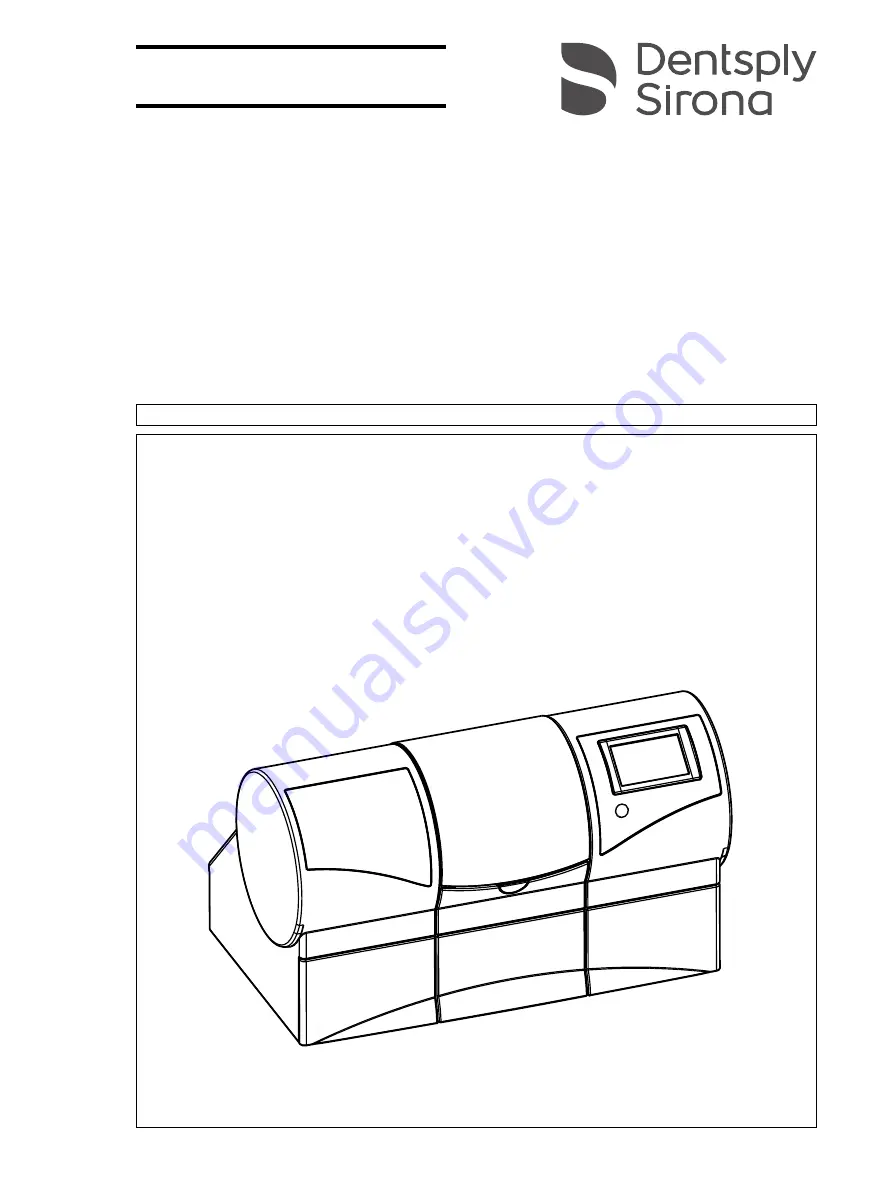
CEREC MC XL Premium Package

(from serial number 300,000)

English

=

Operating Instructions (from serial number 300,000)

This product is covered by one or more of the following US patents:

• US6454629
• US6394880

• US6702649
• US7522764
• US7163443

Содержание CEREC MC XL Premium Package

Страница 1: ...or USA 10 2017 CEREC MC XL Premium Package from serial number 300 000 English Operating Instructions from serial number 300 000 This product is covered by one or more of the following US patents US645...

Страница 2: ...sing chamber door during the machining process 11 4 3 Wireless phone interference with equipment 11 4 4 Disturbance of data transmission 12 5 Installation and startup 13 5 1 Transport and unpacking 13...

Страница 3: ...es 40 6 3 1 1 Grinding 41 6 3 1 2 Milling 42 6 3 1 3 Permitted instrument combinations 43 6 3 2 Preparations 43 6 3 3 Starting the machining processes 43 6 3 4 Ending the machining processes 44 6 3 5...

Страница 4: ...ith base metal and other materials 63 7 8 3 Changing filters on the external tank 63 7 9 Removing water from the unit 67 7 9 1 Procedure for all materials except for base metals 67 7 9 2 Base metal op...

Страница 5: ...ona This device enables you to produce dental restorations e g from ceramic material with a natural appearance CEramic REConstruction Improper use and handling can create hazards and cause damage Plea...

Страница 6: ...material damage please observe the warning and safety information provided in these operating instructions Such information is highlighted as follows Tip Information for simplifying work DANGER An im...

Страница 7: ...this document this refers to a PC for the acquisition unit if present The PC is represented symbolically Please observe our recommendations for PC configuration see System requirements 70 Prerequisit...

Страница 8: ...he following standards apply DIN EN ISO 12100 2011 03 DIN EN 61010 1 2011 07 and DIN EN 61326 1 2013 07 Examples of CE mark for connected products EN 60601 1 2006 based on IEC 60601 1 2005 EN 60950 1...

Страница 9: ...ose If the unit is used for any purpose other than the one mentioned above it may be damaged Intended use also includes compliance with these Operating Instructions and the relevant maintenance instru...

Страница 10: ...OEM spare parts Please request a certificate whenever you have such work performed It should include The type and scope of work Any changes made in the rated parameters or working range Date name of...

Страница 11: ...sories 4 2 Opening the processing chamber door during the machining process 4 3 Wireless phone interference with equipment The use of mobile wireless phones in practice or hospital environments must b...

Страница 12: ...e connection This may become noticeable through a reduction in range and or a slower data transmission rate In extreme cases it will be impossible to establish a wireless connection at all Dentsply Si...

Страница 13: ...packaging for shipment The unit must be drained prior to shipment if it has been operated Removing water from the unit 67 Transport without packaging 5 2 Disposal of packaging materials The packaging...

Страница 14: ...ion slots underneath and at the back of the unit remain unobstructed The distance between the back of the unit and the wall must at least be 10 cm Note that the unit weighs 43 kg The unit must not be...

Страница 15: ...startup Operating Instructions CEREC MC XL Premium Package 5 4 Commissioning b 5 4 1 Functional elements Unit overview Overview of the milling and grinding unit A Processing chamber D ON OFF switch B...

Страница 16: ...age Ports on the back side Connections Processing chamber Processing chamber A Main switch I ON 0 OFF E Communications interface for suction B Fuse cover F Bar code reader connection C Power connectio...

Страница 17: ...5 4 2 Standard accessories 5 4 2 1 Instruments The following instruments are available for milling and grinding purposes When replacing instruments ensure the permitted instrument combinations are use...

Страница 18: ...Torque wrench Clamping format of the force transmission Step Bur 12 S 62 40 167 Grinding Triangular Step Bur 12 62 60 025 Grinding Cyl Pointed Bur 12 S 62 40 159 Grinding Step Bur 20 62 59 597 Grindin...

Страница 19: ...XL Premium Package 5 4 Commissioning b 5 4 3 Touch display description In these Operating Instructions operation is described in such a manner that you can execute and confirm commands via your PC or...

Страница 20: ...Touch display overview 5 4 4 Illumination of the processing chamber The lighting of the processing chamber depends on the machining operation involved A Unit serial number D Pump button Start stop wat...

Страница 21: ...ert the block clamp tool on the left and the bar code reader on the right Connecting the bar code reader Plug the bar code reader into the serial interface to the rear of the milling and grinding unit...

Страница 22: ...network cable Connect the PC to the LAN connection of the unit If problems arise when connecting via a network cable please read the separate instructions Operating the MC XL via LAN 5 4 7 2 Connecti...

Страница 23: ...ton in the system menu 2 Click on the Devices button 3 Click on the Scan for New Devices button All units connected to the PC are recognized In the case of new units you will be prompted to enter a na...

Страница 24: ...appears on the IP address display once the milling and grinding unit has been switched on 6 Click on the Ok button The software attempts to contact the device If the connection fails check the connect...

Страница 25: ...he rear side of the milling and grinding unit B Notes on the suction tube The suction tube is supplied at a length of approx 2 0 m CEREC MC MC X MC XL Premium Package When connecting the suction devic...

Страница 26: ...terminal Note on the power cable The suction system must only be operated with a power cable with a plug system designed for the relevant country Check the voltage specification on the rating plate T...

Страница 27: ...dial A to set the suction power Recommendation Set the suction power to the minimum min To increase the service life of the filter bags you can increase the suction power to the maximum suction power...

Страница 28: ...d the optimum setting take the acquisition unit and place it in the position in which it will be operated that is farthest away from the access point 4 From this position repeat the communication test...

Страница 29: ...AN switch using the additional 10 m LAN network cable All MC XL units connected to the LAN switch can now be operated via WLAN 5 4 7 7 Connecting to the PC via the wireless interface optional The CERE...

Страница 30: ...and grinding units are operated at once the limited data bandwidth may cause processing time delays 5 4 7 7 2 CEREC Radio Device Creating a network The supplied network devices have not as yet been p...

Страница 31: ...ces 3 Switch the existing network device off and on again within one minute After one minute the new network devices will become part of the network 5 4 8 Filling the water tank Water tank The water t...

Страница 32: ...rcuit 10 Fill the water tank up again until the filter inserts are completely immersed up to the bottom edge of the cover thread 5 4 9 Switching the unit ON and OFF NOTICE Damage to surfaces In the un...

Страница 33: ...es a graphic of the milling and grinding unit which tries to contact the PC You can start or stop the water pump by pressing the Pump button This enables you to drain the water circuit without connect...

Страница 34: ...nd startup Dentsply Sirona 5 4 Commissioning Operating Instructions CEREC MC XL Premium Package You can enter or change the IP address here You can confirm the information you have entered by pressing...

Страница 35: ...Disconnect the power cable and the connecting cable from the back side of the unit and stow them away 2 Stow away the calibration tools in the drawer 3 Check the unit for completeness according to the...

Страница 36: ...Chuck Models can only be milled using manual block fixation Second motor set The check mark must be placed in front of Two Bur Sets You can deactivate instrument sets individually A deactivated instr...

Страница 37: ...omatically started when processing zirconium oxide To deactivate dry milling you can remove the check mark once again Deactivation of an instrument set only for units with four motors It is likely tha...

Страница 38: ...re active A dialog box then opens where you can select the instrument set to be calibrated or the two instrument sets to be calibrated consecutively The date of the last calibration is also displayed...

Страница 39: ...clamp tool for this purpose 6 Insert the calibration pins in the motor mount by hand Tighten the corresponding chuck with the torque wrench until a clicking sound can be heard 7 Close the processing c...

Страница 40: ...sing chamber door The dialog box for selecting the instruments then appears 7 Select the inserted instruments and confirm by clicking the Start button in the window on the PC or touch display The moto...

Страница 41: ...inding For grinding purposes use the following instruments as well as the appropriate torque wrench Instrument REF Torque wrench Clamping format of the force transmission Step Bur 12 S 6240167 Triangu...

Страница 42: ...lling 2 Check Activate Instruments and torque wrenches For milling purposes use the following instruments as well as the appropriate torque wrenches Machine type Serial number wet milling Serial numbe...

Страница 43: ...and positioned the restoration in the block Click the Start Milling step The milling and grinding unit moves into position to insert the set screw 6 3 3 Starting the machining processes The instrument...

Страница 44: ...ining processes You can terminate the machining process at any time by clicking the Stop button on the PC or on the touch display WARNING Risk of injury on the remainder of the ceramic block The remai...

Страница 45: ...Reader option in the unit configuration dialog e g for CEREC Zirconia you must use the barcode reader to read the two barcodes To do this hold the bar code reader tilted to a slight angle and move it...

Страница 46: ...B Use the block clamp tool with torque wrench for this purpose The block is pressed laterally against the contact surface of the block fixing and simultaneously pulled in axially The plate of the bloc...

Страница 47: ...s on the block fixing Removing the adapter sleeve 1 Loosen the ball pressure screw 2 Place the block clamp tool in the inner groove D and pull out the adapter sleeve NOTICE Fasten the block tightly If...

Страница 48: ...ers see Changing the filter 62 Clean the manual block fixing according to the cleaning set instructions REF 61 77 161 Clean the clamping cones of the instruments according to the cleaning set instruct...

Страница 49: ...is hose is available separately as a spare part REF 65 89 795 We recommend carrying out this cleaning procedure or the wet milling of a restoration at least once per week if the device is used for dry...

Страница 50: ...process Alternatively you can also wet grind a normal restoration with the same effect 7 You can remove any zirconium oxide deposits in the lower part of the workpiece axis with a nylon brush between...

Страница 51: ...ehind the filter bag 1 Loosen the two knurled nuts on the maintenance cover 2 Remove the lid 3 Remove the filter bag from the nozzle 4 Then release and remove the two Phillips screws on the perforated...

Страница 52: ...contain a biodegradable preservative Despite this however odors may still develop under unfavorable conditions Observe the following Change the water at least once a week With ambient temperatures abo...

Страница 53: ...aces In the undiluted state the coolant additive DENTATEC disintegrates plastic surfaces and can cause discoloration Do not place DENTATEC on the unit Do not spill DENTATEC NOTICE Approved coolant add...

Страница 54: ...ening D 7 Drain the rest of the grinding water 8 Close the drain opening D 9 Turn the tank cap B counter clockwise and take it off 10 Add approx 75 ml of DENTATEC to the tank 11 Fill the tank with wat...

Страница 55: ...er recommended that you use an additional standard tank which is only used for processing base metal materials Tank double filter with CS aperture traffic white spare order no 63 91 895 IMPORTANT Ask...

Страница 56: ...inding slurry The unit is switched on No machining process is running A collecting vessel of approx 10l is available 1 Pull out the water tank at the front of the unit 2 Pan the tank vigorously 5x in...

Страница 57: ...es through the drain opening 5 Close the drain opening D using your thumbs and pan the tank vigorously 5x in circular movements again 6 Empty the residual contents into the collecting vessel provided...

Страница 58: ...rench and pull it out manually 9 NOTICE Do not grease instruments without chuck Insert the new instrument into the motor mount by hand Tighten the corresponding chuck with the torque wrench until a cl...

Страница 59: ...oved media can be downloaded from the internet via the online portal for technical documents You can reach this portal at the address www dentsplysirona com manuals Click on the menu item General docu...

Страница 60: ...tructions regarding restrictions for use 7 6 2 Protection against medicaments Due to their high concentrations and the substances they contain many medicaments can dissolve etch bleach or discolor sur...

Страница 61: ...ected 1 Use a screwdriver to carefully pry off the cover of the fuses on the back side of the unit 2 Pull out the fuse holder 3 Replace the defective fuses 4 Reinsert the fuse holder 5 Close the cover...

Страница 62: ...side and take them out of the tank along with the filter inserts 3 Rinse the water tank 4 Insert the new filters with cover into the tank and screw them tight 5 Fill the tank see Changing the water 52...

Страница 63: ...water tank 57 7 8 3 Changing filters on the external tank Cleaning the plug in tank 1 Pull out the plug in tank 2 Clean the outlet A and then rinse it with water 3 Reinsert the plug in tank Opening t...

Страница 64: ...ng accidentally comes loose you can reattach it by screwing it in counter clockwise 2 Dispose of the filter cartridges with domestic waste 3 Slowly pour the water out of the container into the outlet...

Страница 65: ...ter b 3 Place the clamping ring onto the external water tank with the labeling A facing up 4 Add approx 400 ml of DENTATEC to the tank 5 Fill the tank up to the filling level with water approx 16 lite...

Страница 66: ...mping ring Connecting the External Water Tank 1 Insert the suction connection up to the stop 2 Insert the drain hose up to the stop NOTICE Risk of overflowing Sagging of the drain hose may result in o...

Страница 67: ...to the housing 7 9 2 Base metal operation or mixed operation with base metal and other materials 1 Empty the water tank see Emptying the water tank 56 and insert it back into the unit 2 Switch the uni...

Страница 68: ...er on the tank cap as shown and take off the tank cap by unscrewing it counter clockwise Opening the filter cap The water tank has been pulled out and drained Place the tank cap opener on the filter c...

Страница 69: ...Premium Package 7 10 Using the tank cap opener b Opening the tank drain The water tank has been pulled out Place the tank cap opener on the filter drain as shown and take off the filter drain by unsc...

Страница 70: ...nly compatible with software versions after CEREC SW 4 3 and higher or inLab SW 4 2 5 and higher For all software generations 4 x and higher CEREC AC Bluecam PC hardware version must be LN or higher W...

Страница 71: ...um Package Rated line voltage 100 V 230 V AC Rated power frequency 50 60 Hz Nominal current 1 5 3 5 A Nominal power output 320VA Permissible line voltage fluctuations 10 of nominal voltage Type of pro...

Страница 72: ...d Bur 20 6x Left hand side REF Right hand side Shaper 25 3x dry milling 62 99 395 62 99 387 Finisher 10 3x dry and wet milling Shaper 25 RZ 3x wet milling 64 33 440 Milling possible only with milling...

Страница 73: ...lter unit pack of 6 65 78 095 Filter bag double pack CEREC 63 85 277 HEPA filter 65 89 795 Cleaning hose 64 79 849 Torque wrench spare 64 79 856 Torque wrench spare only for shaper 25 RZ 62 58 987 Bal...

Страница 74: ...many To initiate return of the electrical device please send a disposal request to enretec GmbH You have the following options here Use the Returning an electrical device button under the eom menu ite...

Страница 75: ...suction 16 Connections 16 Cooling water nozzles 59 D Dimensions 71 Disinfectant 60 Disposal of old electrical and electronic devices 74 E enretec GmbH 74 Ethernet LAN port 16 F filter change 62 Order...

Страница 76: ...Product safety 11 Protection class 71 R Rated line voltage 71 Repair 10 S Safety instructions 6 Scope of supply 35 T Temperature range 71 Transport 13 Type designation 71 U Unit installation automati...

Страница 77: ......

Страница 78: ...Sirona Dental Systems GmbH Sprache englisch Printed in Germany D 3439 201 06 10 02 10 2017 Nr 124 428 Sirona Dental Systems GmbH Contact in the USA Fabrikstra e 31 64625 Bensheim Germany Sirona Denta...

Отзывы: