background image

7ML19985GE04

 SITRANS LC500 – OPERATING INSTRUCTIONS 

Page 21

Inst

allat

ion

Installation

Handling Precautions

Notes:

• Installation shall only be performed by qualified personnel and in accordance with 

local governing regulations.

• This product is susceptible to electrostatic discharge. Follow proper grounding 

procedures.


WARNINGS: 

• Disconnect the device before any welding is carried out in the vicinity 

of the instrument. 

• Provide protection when the solid-state switch is activating an 

external relay to prevent possible switch/relay damage resulting from 
inductive spikes generated by the relay coil. (See 

Protection for solid-

state switch

 on page 22 for details.)


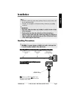
WARNING: To prevent damage, all LC500 units with a rod longer than 
2 m (6.5 ft) must be handled as described below.

When lifting LC500 from a horizontal position, support it at these three points:

Towards the end of 

the rod

Midway along 

the rod

At the process 

connection or flange

Once vertical, LC500 may be held by the process 
connection or flange:

At the process 

connection or flange

Note: Unit shown is LC500 Threaded Rod Version. 
Handling precautions apply to all LC500 units with 
rods longer than 2 m (6.5 ft).

Содержание SITRANS LC500

Страница 1: ...SITRANS Capacitance Transmitters SITRANS LC500 Operating Instructions 05 2012 ...

Страница 2: ...und version and in electronic version We encourage users to purchase authorized bound manuals or to view electronic versions as designed and authored by Siemens Milltronics Process Instruments Siemens Milltronics Process Instruments will not be responsible for the contents of partial or whole reproductions of either bound or electronic versions While we have verified the contents of this manual fo...

Страница 3: ...nfiguration 17 SITRANS LC500 Electrode Probe Characteristics 17 Electrode Assembly 18 Process Connections 18 Seal Types 18 Process Connection and Seal Configuration of SITRANS LC500 18 Pressure and Temperature Considerations 19 Non standard applications 20 Installation 21 Handling Precautions 21 Handling Electrodes 22 Mounting Instructions 22 Protection for solid state switch 22 Process Cautions 2...

Страница 4: ...38 Adjusting the value 38 Transmitter Variables 39 Start up SITRANS LC500 40 Quick Start 40 Menu levels 0 and 1 42 Start up using push button calibration overview 42 Calibration using push button adjustment 43 Calibration using HART 46 Maintenance 50 Test function 50 Inspections 50 Troubleshooting SITRANS LC500 52 Error Messages and Error Codes 53 Error Messages push button operation 53 Error Code...

Страница 5: ...80 Damping information 80 Non volatile Memory Data Storage 80 MultiDrop operation 81 Burst mode 81 Units conversions 81 Additional Universal Command Specifications 81 Appendix D Block Diagram and Correlation table mA to 82 Correlation Table 0 100 to 4 20 mA or 20 4 mA 83 Appendix E SITRANS LC500 alternate versions and application details 84 Cable version non insulated 7ML5513 84 Cable version insu...

Страница 6: ...v Table of Contents Appendix F Approvals 105 NAMUR recommendation NE 43 105 Control Drawing FM CSA Approval 106 SITRANS LC500 106 Glossary 107 Index 109 Quick Reference SITRANS LC500 111 Quick Start 111 ...

Страница 7: ...s important information about the product or that part of the operating manual Alternating Current Direct Current Earth ground Terminal Protective Earth Terminal Frame or Chassis Terminal Cathodic protection resulting in a potential difference for example between the ground on the instrument and the potential of the vessel or tank Notes Please follow the installation and operating procedures for a...

Страница 8: ...port is available 24 hours a day To find your local Siemens Automation Office address phone number and fax number go to www siemens com automation partner Click on the tab Contacts by Product then drill down to find your product group Process Automation Process Instrumentation Level Measuring Instruments Select the team Technical Support Click on Next Click on the appropriate continent then select...

Страница 9: ...Vacuum HART Highway Addressable Remote Transducer LRV Lower Range Value value for 0 4 mA LSL Lower Sensor Limit below which no PV is anticipated F micro Farads 10 6 Farad s micro Seconds 10 6 Seconds PED Pressure Equipment Directive safety approval pF pico Farads 10 12 Farad ppm parts per million PV Primary Variable measured value Stilling Well Grounded metal tube with openings SV Secondary Variab...

Страница 10: ...nterrupting the process and the probe shield design eliminates the need for frequent recalibration SITRANS LC500 can be used as a level controller by connecting the mA output and or the solid state switch to a relay and activating a pump via an auxiliary power circuit The SITRANS LC500 is equipped with Smart 2 wire transmitter Remote adjustable commissioning control capabilities via HART2 Analog 2...

Страница 11: ...C 40 to 158 o F for T6 40 to 85 o C 40 to 185 o F for T5 to T1 Relative humidity suitable for outdoor Type 4X NEMA 4X IP65 IP68 enclosure Installation category I Pollution degree 4 Performance Measurement range Transmitter type MSP 2002 2 1 to 3300 pF Minimum span 3 3 pF Measurement frequency 420 kHz Cx 0 pF Accuracy deviation 0 1 of actual measurement value Non linearity 0 1 full scale Repeatabil...

Страница 12: ... 000 Current loop continuous signal 4 to 20 mA 20 to 4 mA 2 state functionality 4 or 20 mA 20 or 4 mA on or off time delay 1 to 100 sec activating de activating adjustable hysteresis on off 0 to 100 min 1 of range Solid state switch time delay 1 to 100 sec activating de activating adjustable hysteresis on off 0 to 100 min 1 of range max switching voltage 30 V DC 30 V peak AC max load current 82 mA...

Страница 13: ...Probe insulation PFA Enamel2 Wetted Parts Probe insulation PFA Enamel Threaded connection AISI 316 L stainless steel Flange AISI 316 L stainless steel or Teflon3 covered Enclosure electronic construction aluminum epoxy coated diameter 160 mm 6 3 cable entry 2 x 1 2 NPT ingress protection Type 4X NEMA 4X IP65 IP68 Weight Depends on configuration Example rod PFA insulated 16 mm 0 63 dia 1 m 39 4 ins...

Страница 14: ...Register of Shipping Categories ENV1 ENV2 ENV3 ENV5 1 Please refer to page 19 Temperature Pressure Curve chart for specific combi nations of temperature and pressure Notes See Appendix F Approvals on page 105 for details of certification Intrinsically Safe IS approval ATEX II 1 G EEx ia IIC T4 T6 FM CSA Class I Div 1 Gr A B C D T4 no longer available For LC500 devices purchased prior to June 2008 ...

Страница 15: ...relative dielectric constant of air vacuum is 1 all other materials have a higher value The SITRANS LC500 variable frequency oscillator The SITRANS LC500 probe is equipped with a variable frequency oscillator which responds to the capacitance a change in capacitance is registered as a change in frequency The relationship between capacitance and frequency is inverse resulting in high resolution and...

Страница 16: ...nce is from the probe to the tank wall The tank wall is the reference electrode and it must be connected to the ground point on the instrument If the vessel contents are conductive the electrode must be insulated In this case the dielectric is the insulation layer and the interface between the conductive contents and the insulating sleeve acts as the reference electrode This reduces the separation...

Страница 17: ... Its diameter is somewhat larger than that of the electrode depending on the application The stilling well can either be integral to the SITRANS LC 500 or it may be part of the tank1 The SITRANS LC500 electrode The SITRANS LC500 electrode comprising a measurement section and an active shield section is the primary sensor of the system It supplies the electrical capacitance value of the measurement...

Страница 18: ...ative to the total length of the electrode specify a short measurement section This increases the achievable resolution of the measurement since any change in level will be greater relative to the length of the measurement section Measuring Circuit Measuring Circuit Conventional Capacitance Measurement SITRANS LC500 with Active Shield C1 C2 C3 R C1 C2 C3 Ca C1 C2 C3 Ca Cm R Ca Ca Cm Ca Ca Cm Cm R ...

Страница 19: ...100 URV can be set anywhere within the measurement range 1 The loop current provides either a an analog signal a reading proportional to level PV under normal conditions an out of limits display ooL alternating with PV in fault conditions if the process level exceeds the limit settings USL or LSL or b in 2 state mode provides a mA output 4 mA or 20 mA output for 0 and 100 under normal conditions a...

Страница 20: ...enu 18 take precedence over the threshold settings menus 07 and 17 Level Measurement The continuous 4 20 or 20 4 mA signal is proportional to the surface level of the product with an accuracy of 0 1 of the actual measurement for example 1mm m Typically Lower Range Value LRV 0 is set to 4 mA and Upper Range Value URV 100 is set to 20 mA but the reverse is possible if required The measurement takes ...

Страница 21: ... 101 Switch action 2 state Switch The mA output can be used as a 2 state switch set to either 4 or 20 mA It can be set to go to 4 mA if the probe is covered and 20 mA if the probe is uncovered or the reverse Solid state Switch The solid state output can be set to contact open or contact closed with a covered probe Adjustable hysteresis and time delay The adjustable hysteresis and time delay settin...

Страница 22: ...A or 20 5 mA If the process value is outside the Upper or Lower Sensor Limits this will be registered as a fault failure Depending on the setting chosen for 2 state Fault Signalling menu 08 the signal will go to either 3 6 mA F Lo or to 22 mA F Hi If you do not use communications to receive status information we recommend enabling analog fault signalling menu 08 in order to be warned if a fault or...

Страница 23: ...rm the complete electrode This is not the case for cable electrodes or electrodes with ceramic enamel insulation The sum of the active shield length and the measurement length is the total insertion length The active shield design provides continuous immunity from changes in conditions at the top of the vessel where levels of vapors dust and condensation may be constantly changing The design of th...

Страница 24: ... representative for details or check our website at www siemens milltronics com Seal Types The basic internal seal for the SITRANS LC500 has a conical shaped preloaded pressure leak resistant construction Up to three levels of seal protection are implemented depending on the integrity requirements of the application A single or double cone internal seal forms one or two barriers against leaking an...

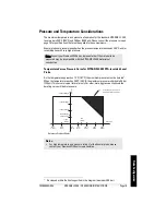
Страница 25: ...ches 200 C 392 F the maximum pressure is limited to 50 bar 725 psi This curve is typical for water only For other more aggressive chemicals the derating curve will be more severe Note Consult your Siemens Milltronics representative if the material to be measured may be incompatible with the SITRANS LC500 materials of construction 1 Decreased within the limits specified in the diagram maximum 200 b...

Страница 26: ...ate configurations see Appendix E SITRANS LC500 alternate versions and application details on page 84 Non Standard Application SITRANS LC500 Configuration Non metallic tanks with both conducting and non conducting liquids Use stilling well for second electrode reference Non conducting liquids in spherical and horizontal cylindrical tanks Use a stilling well as linearizer Highly corrosive materials...

Страница 27: ...xternal relay to prevent possible switch relay damage resulting from inductive spikes generated by the relay coil See Protection for solid state switch on page 22 for details WARNING To prevent damage all LC500 units with a rod longer than 2 m 6 5 ft must be handled as described below When lifting LC500 from a horizontal position support it at these three points Towards the end of the rod Midway a...

Страница 28: ...ng packing and installation2 Any damage to the electrode can prevent proper performance ATEX 95 Precautions MUST be taken to avoid ignition due to hazardous electrostatic discharges a Where an isolated probe is used in gas vapor or a non conductive liquid that is potentially explosive requiring apparatus group IIC equipment b Where the probe is used in a potentially explosive dusty atmosphere 1 No...

Страница 29: ...sign only Various process connection materials Both Rod and Cable versions See Appendix E SITRANS LC500 alternate versions and application details page 84 onward for details on dimensions and for application examples CAUTION Consider material surface configuration when installing unit CAUTIONS With a centrally mounted cable version take care that the tensile load does not exceed probe or vessel ra...

Страница 30: ...gulations valid in your country for electrical installations in potentially explosive atmospheres Ensure that the available power supply complies with the power supply specified on the product nameplate and specified in the examination certificate valid in your country Dust proof protection caps in the cable inlets must be replaced by suitable screw type glands or dummy plugs which are appropriate...

Страница 31: ...e correct instrumentation cable you need to know the cable length and the measurement resistance select a cable that will give you a capacitance time constant of less than 65 μSec Notes To maintain reliable transfer of the HART modem signals the RC1 time constant of the connections should be less than 65 μSec For output signals from the SITRANS LC500 only the cable and barrier resistance are relev...

Страница 32: ...For a standard 250 Ohm sensing resistance with a 100 meter cable 250 Ohm 0 0736 Ohm meter 100 m 68 nF 0 1 nF m Since 20 s is less than 65 s 100 meters of this cable is suitable Multi drop applications maximum cable length In a multi drop application the total capacitance of all the devices must be calculated With three devices at 3 x 68 nF the allowable cable length will be considerably limited No...

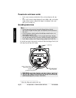
Страница 33: ...land and thread the cable through it 3 Connect the power signal conductor wires to the current loop terminal block any polarity For effective electromagnetic compatibility performance ensure that the filter assembly remains installed When wiring the current loop ensure that each terminal block entry houses a power wire and one line of the filter assembly 4 Ground the enclosure see instructions on ...

Страница 34: ...d braided shield over clamping insert Make sure that braided shield overlaps the O ring by 3 32 2 mm and covers the entry 360 degrees 3 Push clamping insert into body and tighten dome nut Assemble into housing measuring signal mini coaxial cable ground connection point for instrument system ground lug instrument system ground 4 20 mA current loop connection any polarity solid state switch relay an...

Страница 35: ...e middle nut 2 and visually inspect that the armour braid has been successfully clamped between the diaphragm seal armour spigot and the armour clamping ring 3 If armour braid is not clamped repeat assembly Armour braiding should be fitted 360 degrees around the entry 6 Reassemble the middle nut 2 onto the entry component 5 Tighten up the middle nut 2 until hand tight then using a wrench turn the ...

Страница 36: ...ons it is important to have good low resistance reliable connections in this circuit Use a ground connection wire with a sufficiently large diameter relative to its length and not less than 1 mm2 The SITRANS LC500 measurement circuit is completely isolated from the loop circuitry this allows either line of the loop circuit to be grounded if requirements for Ex safety are followed and if the power ...

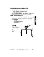
Страница 37: ...trates Safety Grounding System Grounding referencing For the measuring system to function correctly the reference electrode must be properly grounded Make sure that there is a reliable connection from the instrument housing to the reference electrode usually a metal tank Some common applications involving system grounding include metal tanks metal tanks cathodically protected non conductive tanks ...

Страница 38: ...ed metal tanks are never directly grounded However the impedance of the supply source is so low that it will not cause any problems The shielding of the loop cable should be grounded at one end only the tank end to avoid short circuiting the cathode protection voltage The ground lug on the SITRANS LC 500 can be connected to the tank as shown See page 30 for further grounding details metal ground l...

Страница 39: ... galvanically separated inputs for each measurement channel the grounding method can be chosen as required In hazardous applications a Stahl type barrier is required and it is typically mounted on a DIN rail inside a customer supplied enclosure located in the non hazardous area Example 1 If no specific Ex conditions apply the SITRANS LC500 can be directly connected to the DCS The supply voltage ho...

Страница 40: ...8 to 20 5 mA If the process exceeds its normal limits but is not in a fault or failure situation the signal current will be outside the measurement range 4 to 20 mA but will be limited to either 3 8 or 20 5 mA If a fault or a failure is detected the signal current is set to either 3 6 mA or 22 mA depending on the settings you have chosen This feature may be disabled by the user 1 Depending on the ...

Страница 41: ...olid state output is a polarity independent switch output The solid state switch has two possible functions it can be activated deactivated when the product level reaches the upper lower threshold settings set in menus 15 and 16 or it can be activated if a fault or failure is detected2 set in menu 18 See page 102 for an illustration of a typical application using SITRANS LC 500 as a level indicato...

Страница 42: ...rent is limited by a proper load Due to the limited switching capabilities of the solid state switch component an auxiliary relay must be applied when switching high current high voltage apparatus WARNING When the solid state switch is activating an external relay protection diodes must be connected in the correct polarity across the relay coil to prevent possible switch relay damage resulting fro...

Страница 43: ...Value URV and Lower Range Value LRV should be within the USL to LSL range but can be set anywhere within that range An interruption of the measuring connection will be detected a loose or interrupted connection results in up to 0 5 pF capacitance which is below the adjusted LSL and thus signals a FAULT condition TV1 Units UNDEFINED TV1 LRV 0 switch position 0 E TV1 TV URV 1 0 switch position 0 F T...

Страница 44: ...together with the associated menu items is shown in Appendix B LCD display examples on page 75 The LCD will hold information for a long time even when not refreshed for example if there is a loss of power The heartbeat indicator blinks continuously whenever the device is working A still heartbeat signals that the device has stopped working solid state switch relay any polarity current loop connect...

Страница 45: ... page 59 0F Upper Range Value page 60 00 Dynamic Value PV Transmitter Variable Value page 60 02 Max Min Recorded Value page 61 01 Transmitter Variable select for PV page 61 03 Upper Threshold Delay 2 state mode Analog Output Signalling loop current page 63 04 Lower Threshold Delay 2 state mode page 63 05 Upper Threshold Setting 2 state mode page 64 06 Lower Threshold Setting 2 state mode page 65 0...

Страница 46: ...or special applications For a table showing the combinations of rotary switch positions and button presses used to carry out different functions see page 41 Access to a menu item 1 First select Menu LEVEL 0 or Menu LEVEL 1 2 Turn the rotary switch to the number of the desired item Adjusting the value 1 Select a menu item 2 Press the RED or BLUE push button to adjust the value up or down acceptance...

Страница 47: ...smitter Variable 0 TV0 is the capacitance as measured by the device Transmitter Variable 1 TV1 is a computed variable the dynamic value is a computed derivative from the range settings for TV0 Transmitter Variable User defined Functions Units TV0 URV LRV Damping USL and LSL pF TV1 Can be user defined ...

Страница 48: ...iption of each menu item see Appendix A page 55 Quick Start Sequence 1 Calibrate the 0 setting LRV lower range value menu 0E For instruments without a stilling well the 0 setting needs to be calibrated after the device is installed and with the tank vessel empty Calibration is also sometimes neces sary after installing a SITRANS LC500 fitted with a stilling well although in most cases the 0 settin...

Страница 49: ...100 Preset Upper Threshold Point to 75 Preset Lower Threshold Point to 25 Set Analog Range 4 to 20 mA Anl Fault signal Disable Set to 1 Set to 1 Preset Lower Limit to Actual PV Preset Upper Limit to Actual PV URV LRV Min LRV Actual Value PV URV Actual Value PV Default TVO 00 00 75 25 Analog Disabled 1 0 1 1 666 pF 3300 pF 3300 pF 0 pF 3300 pF Menu LEVEL 1 10 to 1F Units PV Units Numerical Factory ...

Страница 50: ...yed in the top left corner of the LCD 4 When the button is released the LCD displays PV In menu 00 or 10 to see the current menu level selection briefly press one of the buttons less than a second the current selection is momentarily displayed Start up using push button calibration overview Check that Keylock level is set to enable calibration If required change the transmitter variable select uni...

Страница 51: ...s the 0 setting is calibrated at the factory 1 Set value for 0 LRV units must be pF Menu 01 must read Pv 0 a Bring the product level to the height that corresponds to 0 b Set the rotary switch to E Empty c Press both buttons and hold for about 1 second the 0 point is now set Calibrate the 100 setting URV upper range value menu 0F method 1 if it is possible to bring the actual product level to 100 ...

Страница 52: ... press to increase the span which will reduce the percentage until the value reaches 70 00 If the steps are too big you need to change the stepsize menu 09 to a lower value Changing stepsize value menu 09 The factory setting is 1 the LCD displays U 1 0 Set rotary switch to 09 and press BLUE button to reduce stepsize values range from 0 01 to 1 000 Example LCD displays 78 00 percent Known percent o...

Страница 53: ...a table showing the different functions available and the combinations of switch position and button presses used to carry out these functions see page 41 For a detailed list of menu items see Appendix A Menu Groups on page 55 Notes During normal operation the 4 and or 20 mA point can be calibrated at any time If the difference in the capacitance value between the 4 mA point and the 20 mA point is...

Страница 54: ...elect Device setup c Select Diag service d Select Calibration e Select Apply values Display reads Loop should be removed from automatic control Select Ok f Select 4 mA g Select Apply new 4 mA input 2 Bring the level of the product to the level which corresponds with 4 mA a Select Read new value b Select Set as 4 mA value the 4 mA point has now been set c Select 20 mA d Select Apply new 20 mA input...

Страница 55: ...auto Example 3 For situations where the capacitance values are unknown and the level of the product cannot be easily adjusted to 0 and 100 In this case it is necessary to measure the capacitance value at various levels These values can be read in with the 275 communicator 1 Switch on the 275 and establish connection with the SITRANS LC500 a Select Online b Select PV c The measured value can be rea...

Страница 56: ... SITRANS LC500 a Select Online b Select PV The measured value can now be read continuously 2 Write down the measured value in pF assume it is 80 pF Example Assume that the URV is set to 240 pF that the actual value is 17 but the measurement is showing a different value the measured value 80 pF 100 17 83 240 80 pF 60 pF 160 pF 1 927 pF per 83 The capacitance value for 100 URV is 100 1 927 192 7pF T...

Страница 57: ...RV and LRV 141 Read TV1 Units URV and LRV 144 Reset Max Min recorded PV 145 Read Max Min recorded PV 150 Write analog signalling mode 151 Read analog signalling mode 152 Write digital signalling mode 153 Read digital signalling mode 154 Write analog threshold settings 155 Read analog threshold settings 156 Write digital threshold settings 157 Read digital threshold settings 160 Write timers analog...

Страница 58: ...te When the buttons are released the outputs revert to the initial state If no Fault Failure is present and no buttons are pressed the display for menu 11 alternates between two test patterns which together illuminate all the segments of the display If the loop current control is in analog mode the loop current will hold the last value during this test Inspections Under normal circumstances the SI...

Страница 59: ...t goes to the alarm position 3 6 or 22 mA if the coaxial plug is unplugged at menu 00 the LCD should display ooL After the test replace the coaxial plug d Confirm that Menu 18 is set to enable digital fault signalling the LCD should display F cc or F co when buttons are released e Check that the solid state output goes to the alarm position open close if the coaxial plug is unplugged After the tes...

Страница 60: ...enu 01 is set appropriately if Pv 1 changes can only be made via HART If you can change settings reset menu 12 to factory settings press both buttons and the display should read FAC A If the LCD displays a negative reading typically around minus 300 pF this often indicates a short circuit in the probe assembly check the enclosure and make sure no water has got in check that all the connections in ...

Страница 61: ... limits The product level has risen above the Upper Sensor LImit or fallen below the Lower Sensor Limit Error Code Description Cause 32 program memory checksum error Device is faulty 16 signal error the measurement circuitry stopped functioning Possible short circuit in the probe or the device wiring 8 DAC drive failure the current as set by the DAC does not match the value measured by the ADC Pos...

Страница 62: ...Page 54 SITRANS LC500 OPERATING INSTRUCTIONS 7ML19985GE04 Troubleshooting Notes ...

Страница 63: ...imary Variable PV Highest Lowest Recorded Value Transmitter Variable select for PV Transmitter Variables Dynamic Value Menus 00 and 10 Menu 02 Menu 01 Menu 1C see page 60 see page 61 see page 61 see page 62 Analog Output Signalling loop current Upper Threshold Delay Lower Threshold Delay Upper Threshold Setting Lower Threshold Setting Analog Signalling Mode Analog Fault Signalling Menu 03 Menu 04 ...

Страница 64: ...ay or debounce time to change a setting this debounce time is generally around a second but varies from one menu item to another Protection is set at keylock level menu 1F make sure the setting is appropriate The transmitter variable units as pF units user defined or values as percent is set at menu 01 make sure the setting is appropriate Reset to factory settings at menu 12 factory settings are i...

Страница 65: ...level 0 drops below the Lower Sensor Limit the measurement is considered at fault and the LCD displays ooL alternating with PV If the display mode is in this selection is disabled and the LCD displays The transmitter variable on which this menu selection operates is chosen in Menu 01 The increment decrement step size is subject to the setting from Menu 09 1 Set the rotary switch to B 2 Press the R...

Страница 66: ...he unit for overfill or underfill protection where it is impossible to bring the product to those levels in normal process conditions This feature is not normally used for the SITRANS LC500 Overfill protection is used in applications where the probe is normally uncovered Delta Range Setting adds the minimum span to the Lower Range Value the result is used to update the Upper Range Value If the pro...

Страница 67: ... the setting from Menu 09 1 Set the rotary switch to E 2 Press and hold both buttons simultaneously to take the current PV reading as the new setting or Press the RED or BLUE button to step the value up or down or Press and hold a button for a prolonged time to start a repeat function When the new setting exceeds that of the Limit Settings Menu 0C and 0B the new value is rejected and the previous ...

Страница 68: ...ted and the previous value remains unchanged Transmitter Variable Values menu level 0 Dynamic Value Primary Variable PV menu 00 and menu 10 The value for the Primary Variable is displayed as either units or percent of range selected in menu 01 When 2 state mode is selected in menu 07 the LCD display indicates the probe status blinking for an uncovered probe steady for a covered probe If the intern...

Страница 69: ... the LCD indicating menu level 1 Display the Highest Lowest Recorded Value 1 Set the rotary switch to 2 The Highest Lowest recorded values for TV currently selected are displayed alternately 2 Press the RED button to select the Highest recorded value for display or Press the BLUE button to select the Lowest recorded value for display 3 Press both buttons simultaneously for more than one second to ...

Страница 70: ...on allows you to read the values of the dynamic variables TV0 TV1 TV22 and TV3 When no buttons are pressed the LCD displays the dynamic value for TV0 Notes When PV is set to 1 settings cannot be changed using push button adjustment Many settings cannot be changed using push button calibration when PV P 1 The units are pF there is no other option Menu Item Rotary Switch Position Left Arrow Mode Des...

Страница 71: ...r decrease the value or Press and hold a button to start a repeat function or Press and hold both buttons simultaneously to toggle the value between minimum 0 and maximum 100 Lower Threshold Delay 2 state mode The Lower Threshold Setting controls the Deactivation delay the amount of time that has to pass uninterrupted with the probe covered to a level below the Lower Threshold Setting before the t...

Страница 72: ...urrent control Menu 07 must be in 2 state mode for this menu to display the Upper Threshold Setting in percent As an extra identifier an upward ramp is displayed to the right of the value 1 Set the loop current control Menu 07 to 2 state mode 2 Set the rotary switch to 5 3 Press the RED or BLUE button to increase or decrease the value or Press and hold a button to start a repeat function Menu Item...

Страница 73: ... or Press and hold a button to start a repeat function Analog Signalling Mode 2 state menu level 0 The factory setting is for Analog mode the loop current is proportional with the percentage of the range When no buttons are pressed the LCD displays the current mA value 2 state Signalling Mode provides a 4 mA or 20 mA output The settings are relative to a covered probe C Hi selects a 20 mA signal f...

Страница 74: ...by pressing both buttons simultaneously for more than one second The LCD displays C An while the two buttons are pressed and displays the current reading when the buttons are released The loop current will be between 3 8 and 20 5 mA and will saturate to one of these values if the level goes beyond the Upper or Lower range settings Menu Item Affected by Rotary Switch Position Left Arrow Mode Descri...

Страница 75: ... Lo In the case of a fault failure the loop current goes to 3 6 mA Note 2 state mode must be selected at menu 07 This menu selection controls the current loop fault failure signal output This signal has precedence over the settings on Menu 07 Menu Item Rotary Switch Position Left Arrow Description Action Values 08 8 Off 2 state Fault Signalling disabled Press both buttons simultaneously Display sh...

Страница 76: ... the Upper Threshold Setting before the timer expires the timer is restarted When the solid state switch control Menu 17 is disabled menu 13 displays When the solid state switch control is enabled menu 13 displays the Activation delay in seconds As an extra identifier an upward running d is displayed to the right of the value First select the solid state switch output at menu 17 contact open or co...

Страница 77: ... menu 17 contact open or contact closed 1 Set the rotary switch to 4 2 Press the RED or BLUE button to increase or decrease the value 3 or Press and hold a button to start a repeat function 4 or Press both buttons simultaneously to toggle the value between minimum 0 and maximum 100 Upper Threshold Setting solid state output The Upper Threshold Setting is the of range above which the probe is consi...

Страница 78: ... displays the Lower Threshold Setting in percent As an extra identifier a downward ramp is displayed to the right of the value First select the solid state switch output at menu 17 contact open or contact closed 1 Set the rotary switch to 6 2 Press the RED or BLUE button to increase or decrease the value or Press and hold a button to start a repeat function Menu Item Affected by Rotary Switch Posi...

Страница 79: ...lays the current setting in this case S cc 1 Set the rotary switch to 7 2 Press and hold the RED or BLUE button to select contact open or contact closed or Press and hold both buttons to disable this function Menu selections 13 14 15 and 16 set the criteria for delay and threshold that have to be met for a change in output signal Note Menu 18 has precedence over menu 17 1 A colon at the extreme le...

Страница 80: ...es from F cc to F cc If no fault condition exists when the button is released the display shows F cc If you press either button briefly the LCD displays the current setting in this case F cc Set the rotary switch to 8 Press the RED or BLUE button to change the setting The disabled mode can be restored at any time by pressing both buttons simultaneously for more than one second Note This signal has...

Страница 81: ...s are properly processed further on in the PLC DCS system if the normal state is non alarm changing the state should generate an alarm The outputs stay in the opposite state as long as both buttons are pressed Factory Settings Displays whether the factory settings are still in place or how much they have been changed and allows you to restore the factory settings Set the rotary switch to 2 To rest...

Страница 82: ...t a value by pressing two buttons simultaneously Protection level 2 disables the ability to change a value by stepping it up or down Protection level 3 completely disables all changing of values 1 Set the rotary switch to F 2 Press the RED or BLUE button to change the setting Menu Item Rotary Switch Position Left Arrow Description Mode Values 19 9 On Range Inversion normal Display shows nor invert...

Страница 83: ...due to Faults are disabled Current loop current goes to 22 mA when Fault detected Current loop current goes to 3 6 mA when Fault detected Current loop output in Analog proportional mode Indicator for range operation normal URV LRV Indicator for range operation inverted URV LRV Output out of limits PV outside Variable Limits Indicator for Factory Set all parameters are original Indicator for Factor...

Страница 84: ...ator must have the HART Device Descriptor for the unit in question HART DD s are controlled by the HART Communications Foundation The HART DD for the SITRANS LC500 will be released in 2003 Please check availability with the HART Communications Foundation Older versions of the library will have to be updated in order to use all the features in the SITRANS LC500 Simatic Process Device Manager PDM Th...

Страница 85: ...age Date Universal revision Transmitter revision Software revision Polling address Request preambles High calibration level Low calibration level Applied rerange Keypad rerange Zero correction Measuring elements menu Signal conditioning menu Output conditioning menu Device info menu PV upper sensor limit PV lower sensor limit PV minimum span PV sensor units PV Upper range value PV Lower range valu...

Страница 86: ...nitialisation cycle is complete this can occur after a power loss or as a result of a watchdog reset Bit 4 Extended Status Available When any of the extended status bits is set this flag is raised Use command 48 to get detailed status information Bit 3 Output Current Fixed This bit is set as long as the Primary Variable Analog Output is set to a fixed value Bit 2 Primary Variable Analog Output Sat...

Страница 87: ... Class 3 3 Read Dynamic Variables and PV Current Universal 33 Read Selected Dynamic Variables Common Practice 48 Read Additional Transmitter Status Common Practice 50 Read Dynamic Variable Assignments Common Practice Conformance Class 4 34 Write PV Damping Value Common Practice 35 Write Primary Variable Range Values 36 Set Primary Variable Upper Range Value 37 Set Primary Variable Lower Range Valu...

Страница 88: ...ild up on Sensor 130 Read Failsafe Mode selection 131 Return Device Config Info 132 Write Variable Upper Lower Limit Values 133 Read Variable Upper Lower Limit Values 134 Write Keylock Value 135 Read Keylock Value 138 Write Simulation Timer and Value 139 Read Simulation Timer and Value 140 Write S V Units and Range Values 141 Read S V Unites and Range Values 144 Reset recorded PV min max values ba...

Страница 89: ... and Value with Command 140 The Transmitter Variable Range Values may be read at any time with Command 141 The value returned as Secondary Variable S V is the result of the following calculation TV1 TV0 Dynamic Range Value in percent x TV 1 URV TV 1 LRV TV 1 LRV This method provides a means of converting TV 0 which is always in pF to alternative units level or volume Additional Universal Command S...

Страница 90: ...old menu15 Delay menu 03 Lower Threshold menu 06 Lower Threshold menu 16 Delay menu 04 Delay menu 13 Delay menu 14 status 2 state Digital Signalling Mode menu 17 Solid State Output Analog Signal Analog Fault Failure menu 08 Current loop Fault sensor pF TV0 Fault TV1 Fault Fault reset reset reset reset TV0 USL TV0 LSL TV0 URV TV0 LRV TV1 URV TV1 LRV TV1 USL TV1 LSL TV1 damping TV0 damping SITRANS L...

Страница 91: ... 0 100 to 4 20 mA or 20 4 mA Range 0 100 Current in mA Range 100 0 0 4 0 100 5 4 8 95 10 5 6 90 15 6 4 85 20 7 2 80 25 8 0 75 30 8 8 70 35 9 6 65 40 10 4 60 45 11 2 55 50 12 0 50 55 12 8 45 60 13 6 40 65 14 4 35 70 15 2 30 75 16 0 25 80 16 8 20 85 17 6 15 90 18 4 10 95 19 2 5 100 20 0 0 ...

Страница 92: ...e media only Cable can be shortened on site Weight is included in measuring length transmitter electronics stainless steel cable ø 6 mm 0 24 stainless steel weight ø 32 mm 1 26 250 mm 9 84 Y01 insertion length max 35000 mm 1378 min 1000 mm 39 40 measuring length transmitter electronics stainless steel cable ø 6 mm 0 24 stainless steel weight ø 32 mm 1 26 250 mm 9 84 Y01 insertion length max 35000 ...

Страница 93: ...insertion length max 35000 mm 1378 min 1000 mm 39 40 measuring length ø 9 mm 0 35 ø 34 5 mm 1 36 350 mm 13 78 mounting eye ø 12 mm 0 47 ø 25 mm 0 98 20 mm 0 79 Option for mounting eye only available for PFA insulated cable PFA insulated probe ø 9 mm 0 35 stainless steel weight ø 34 5 mm 1 36 350 mm 13 78 measuring length Y01 insertion length max 35000 mm 1378 Option for mounting eye only available...

Страница 94: ...gth measuring length mounting eye ø 12 mm 0 47 ø 25 mm 0 98 20 mm 0 79 Mounting eye option 63 mm 2 48 92 mm 3 62 Y01 insertion length 2 max 35000 mm 1378 20 mm 0 79 GK Mounting eye option 20 mm 0 79 ø 12 mm 0 47 ø 25 mm 0 98 mounting eye Y01 insertion length 2 max 35000 mm 1378 min 5000 mm 197 Y02 Inactive length 63 mm 2 48 92 mm 3 62 measuring length 92 mm 3 62 ø 48 mm 1 88 ø 16 mm 0 63 stainless...

Страница 95: ... mm 3 62 Threaded Flanged stainless steel flexible tube ø 24 mm 0 94 ø 35 mm 1 37 Y02 Inactive length measuring length ø 100 mm 3 9 Mounting eye option Y01 insertion length 2 max 35000 mm 1378 15 mm 0 60 ø 40 mm 1 57 54 mm 2 12 inactive tip stainless steel flexible tube ø 40 mm 1 57 ø 24 mm 0 94 ø 35 mm 1 37 15 mm 0 60 Mounting eye option measuring length 54 mm 2 12 ø 100 mm 3 9 inactive tip Y02 I...

Страница 96: ...uring length 15 mm 0 59 Threaded Flanged transmitter electronics PFA insulated probe ø 16 mm 0 63 or ø 24 mm 0 94 20 mm 0 79 Y01 insertion length min 200 mm 7 87 max 3500 mm 138 ø 16 mm 0 63 min 200 mm 7 87 max 5500 mm 216 ø 24 mm 0 94 measuring length 1 Y02 1 205 mm 8 1 transmitter electronics PFA insulated probe ø 16 mm 0 63 or ø 24 mm 0 94 Y02 measuring length 205 mm 8 1 Typical Y01 insertion l...

Страница 97: ...ng well vent holes or optional slots PFA insulated probe ø 16 mm 0 63 or ø 24 mm 0 94 ø 35 mm 1 38 or ø 48 mm 1 89 Y02 1 measuring length 1 Y01 insertion length min 200 mm 7 87 max 3500 mm 138 ø 16 mm 0 63 min 200 mm 7 87 max 5500 mm 216 ø 24 mm 0 94 stainless steel stilling well vent holes or optional slots PFA insulated probe ø 16 mm 0 63 or ø 24 mm 0 94 ø 35 mm 1 38 or ø 48 mm 1 89 Y02 1 Y01 in...

Страница 98: ...d length 100 mm 3 94 minimum measuring length 250 mm 9 84 Threaded Flanged enamel probe ø 40 mm 1 57 ø 16 mm 0 63 205 mm 8 1 Y01 insertion length min 250 mm 9 84 max 1500 mm 59 06 Y02 1 measuring length 1 Y02 1 measuring length 1 Y01 insertion length min 250 mm 9 84 max 1500 mm 59 06 ø 40 mm 1 57 enamel probe ø 16 mm 0 63 ...

Страница 99: ...ainless steel stilling well vent holes or optional slots enamel probe ø 16 mm 0 63 205 mm 8 1 Y01 insertion length min 250 mm 9 84 max 1500 mm 59 06 measuring length 1 Y02 1 ø 40 mm 1 57 30 mm 1 18 Inactive tip Y02 1 Y01 insertion length min 250 mm 9 84 max 1500 mm 59 06 vent holes or optional slots stainless steel stilling well enamel probe ø 16 mm 0 63 ø 40 mm 1 57 measuring length 1 30 mm 1 18 ...

Страница 100: ...al purpose approval only general purpose approval only stainless steel flexible tube 150 mm 6 0 205 mm 8 1 M20 160 mm 6 3 NPT 230 mm 9 1 With explosion proof seal option all versions 270 mm 10 6 thermal isolator 430 mm 16 9 With thermal isolator option all versions 205 mm 8 1 M20 160 mm 6 3 NPT 230 mm 9 1 With explosion proof seal option all versions With thermal isolator option all versions 270 m...

Страница 101: ...E flange facing option Single piece flange only 7ML5517 Notes All measurements are given in mm One 1 inch 25 4 mm For details see drawings technical data and measuring probe details on pages 84 to 100 raised face flange PTFE flange facing No stilling well or enamel probe available with this option ...

Страница 102: ...e thickness b 3 00 0 00 Face thickness c 0 5 150 lb 1 107 95 79 25 15 88 4 14 29 2 0 1 127 00 98 55 15 88 4 17 46 2 0 2 152 40 120 65 19 05 4 19 05 2 0 3 190 50 152 40 19 05 4 23 85 2 0 4 228 60 190 50 19 05 8 23 85 2 0 6 279 40 241 30 22 22 8 25 40 2 0 300 lb 1 123 95 88 90 19 05 4 15 75 2 0 1 155 45 114 30 22 22 4 19 05 2 0 2 165 10 127 00 19 05 8 20 57 2 0 3 209 55 168 15 22 22 8 26 92 2 0 4 25...

Страница 103: ... 215 90 25 40 8 38 10 7 0 6 355 60 292 10 28 58 12 47 75 7 0 900 lb 2 215 90 165 10 25 40 8 38 10 7 0 3 241 30 190 50 25 40 8 38 10 7 0 4 292 10 234 95 31 75 8 44 45 7 0 6 381 00 317 50 31 75 12 55 63 7 0 Welded Raised Face Flange cont d Flange class Nominal pipe size Outside diameter øD 2 0 Bolt hole Circle øK 0 80 Bolt hole diameter øL 0 30 x N Number of bolt holes N Flange thickness b 3 00 0 00...

Страница 104: ...øL 0 3 x N Number of bolt holes N Flange thickness b 1 0 0 0 PN16 DN25 115 0 85 0 14 0 4 18 0 DN40 150 0 110 0 18 0 4 18 0 DN50 165 0 125 0 18 0 4 18 0 DN80 200 0 160 0 18 0 8 20 0 DN100 220 0 180 0 18 0 8 20 0 DN125 250 0 210 0 18 0 8 22 0 PN40 DN25 115 0 85 0 14 0 4 18 0 DN40 150 0 110 0 18 0 4 18 0 DN50 165 0 125 0 18 0 4 20 0 DN80 200 0 160 0 18 0 8 24 0 DN100 235 0 190 0 22 0 8 24 0 DN125 270...

Страница 105: ... 22 0 4 26 0 DN80 215 0 170 0 22 0 8 28 0 DN100 250 0 200 0 26 0 8 30 0 DN125 295 0 240 0 30 0 8 34 0 Welded Flat Face Flange cont d Flange class Nominal pipe size Outside diameter øD 2 0 Bolt hole Circle øK 1 0 Bolt hole diameter øL 0 3 x N Number of bolt holes N Flange thickness b 1 0 0 0 ...

Страница 106: ...pe size Outside diameter øD 1 0 Bolt hole Circle øK 0 8 Bolt hole diameter øL 0 3 Flange thickness b 3 0 0 0 Face thickness c 0 0 0 5 PTFE facing thickness d 150 lb 1 127 0 98 55 15 88 15 75 2 0 2 0 2 152 40 120 65 19 05 17 53 2 0 2 0 3 190 50 152 40 19 05 22 35 2 0 2 0 4 228 60 190 50 19 05 22 35 2 0 2 0 6 279 40 241 30 22 22 23 88 2 0 2 0 A A SECTION A A b d c øL øK øD ...

Страница 107: ...69 75 22 22 35 05 2 0 2 0 600 lb 1 155 45 114 30 22 22 22 35 7 0 2 0 2 165 10 127 00 19 05 25 40 7 0 2 0 3 209 55 168 15 22 22 31 75 7 0 2 0 4 273 05 215 90 25 40 38 10 7 0 2 0 6 355 60 292 10 28 58 47 75 7 0 2 0 Single Piece Raised Face Flange cont d Flange class Nominal pipe size Outside diameter øD 1 0 Bolt hole Circle øK 0 8 Bolt hole diameter øL 0 3 Flange thickness b 3 0 0 0 Face thickness c...

Страница 108: ...ness b1 1 0 0 0 Face thickness c 0 0 0 5 PTFE facing thickness d PN16 DN40 150 0 110 0 18 0 18 0 2 0 2 0 DN50 165 0 125 0 18 0 18 0 2 0 2 0 DN80 200 0 160 0 18 0 20 0 2 0 2 0 DN100 220 0 180 0 18 0 20 0 2 0 2 0 DN125 250 0 210 0 18 0 22 0 2 0 2 0 PN40 DN40 150 0 110 0 18 0 18 0 2 0 2 0 DN50 165 0 125 0 18 0 20 0 2 0 2 0 DN80 200 0 160 0 18 0 24 0 2 0 2 0 DN100 235 0 190 0 22 0 24 0 2 0 2 0 DN125 2...

Страница 109: ...imensions in meters or dimensions in feet The initial capacitance value at 0 probe in air is 12 7 pF and the capacitance value for 100 tank filled with oil is 25 4 pF After calibration 12 7 pF 0 4 mA or 20 mA 25 4 pF 100 20 mA or 4 mA C 24 L Log D d pF SITRANS LC500 0 25 m 0 82 L 0 95 m 3 12 D 1 0 m 3 28 d 16 mm 0 05 Where C capacitance value in pF r relative dielectric constant L active measureme...

Страница 110: ...necessary by applying Damping menu 0A the update value for Damping is controlled by menu 09 Example The level is to be held between 90 and 8 For this slightly larger tank the capacitance ranges from 16 6 pF for 0 probe in air to 33 2 pF for 100 tank filled with oil After calibration 16 6 pF 0 4 mA or 20 mA 33 2 pF 100 20 mA or 4 mA Cair air 7 32 4 5 Log 60 0 63 pF 16 6pF Coil oil 7 32 4 5 Log 60 0...

Страница 111: ...When the level drops to 8 the solid state output is opened the auxiliary circuit is deactivated and the pump stops Application Analog fault signalling 2 state output In 2 state mode the loop current signals whether the probe is covered or uncovered and the continuous level measurement is unavailable 2 state mode provides a 4 mA or 20 mA output to menu 07 when the level reaches one of the threshold...

Страница 112: ...8 0 USL is set to 83 50 pF Menu 0C reads 83 50 LSL is set to 7 3 pF Menu 0B reads 7 30 When the process level reaches 90 the probe is considered covered and the output will be 20 mA If the level exceeds USL the output will be 22 mA When the process level drops to 8 the probe is considered uncovered and the output will switch to 4 mA If the level drops below LSL the fault signal will be 22 mA 1 F H...

Страница 113: ...signal should be within the range of 3 8 to 20 5 mA failure signalling For failure information which indicates a failure in the measuring system1 the current signal should be in the range of either 0 to 3 6 mA or 21 mA or greater The application will determine which of these two ranges is more desirable The SITRANS LC500 can be set for 3 6 mA or 22 mA as required2 1 It may also signal a process le...

Страница 114: ...For Canada Installation must be in accordance with the Canadian Electrical Code Section 18 3 FM Installation must be in accordance with the National Electrical Code ANSI NFPA 70 and ANSI ISA RP12 6 1 Two FMRC or CSA approved single or dual channel barriers which meet the voltage Voc or Vt and current Isc or It parameters shown in the tables for the appropriate group can be used The Ca and La Entit...

Страница 115: ... to store electrical potential energy under the influence of an electric field This is measured by the ratio of the capacitance of a condenser with the material as dielectric to its capacitance with vacuum as dielectric The value is usually given relative to a vacuum dry air the dielectric constant of air is 11 immiscible incapable of mixing or attaining homogeneity implicit for example in the uni...

Страница 116: ...Page 108 SITRANS LC500 OPERATING INSTRUCTIONS 7ML19985GE04 Glossary Notes ...

Страница 117: ...cautions 22 external relay protection for solid state switch 34 F factory settings restoring 73 values 34 Flange Standards 100 flanges sizes 93 G grounding safety grounding examples 30 system grounding examples 29 H HART conformance and command class 79 documentation 76 information 76 response code information 78 setup 46 HART communications detailed information 76 I Identifications and Abbreviati...

Страница 118: ...atic Process Device Manager PDM details 76 solid state switch diode protection details 28 solid state switch protection connect diode 34 requirement 21 specifications wetted parts 7 Standard Level Version features 23 Standard S Series Threaded Versions 84 88 92 start up calibration instructions 40 supply voltage requirements 24 system grounding referencing 29 T test function details 50 transmitter...

Страница 119: ...ng LRV lower range value menu 0E For instruments without a stilling well the 0 setting needs to be calibrated after the device is installed and with the tank vessel empty Calibration is also sometimes neces sary after installing a SITRANS LC500 fitted with a stilling well although in most cases the 0 setting is calibrated at the factory Set value for 0 LRV units must be pF Menu 01 must read Pv 0 a...

Страница 120: ...100 Preset Upper Threshold Point to 75 Preset Lower Threshold Point to 25 Set Analog Range 4 to 20 mA Anl Fault signal Disable Set to 1 Set to 1 Preset Lower Limit to Actual PV Preset Upper Limit to Actual PV URV LRV Min LRV Actual Value PV URV Actual Value PV Default TVO 00 00 75 25 Analog Disabled 1 0 1 1 666 pF 3300 pF 3300 pF 0 pF 3300 pF Menu LEVEL 1 10 to 1F Units PV Units Numerical Factory ...

Страница 121: ...emens com level For more information www siemens com processautomation Siemens AG Industry Sector 1954 Technology Drive P O Box 4225 Peterborough ON Canada K9J 7B1 Subject to change without prior notice 7ML19985GE04 Rev 4 0 email techpubs smpi siemens com Siemens AG 2012 7ml19985GE04 ...

Отзывы: