


Page 12
SITRANS LC500 – OPERATING INSTRUCTIONS
7ML19985GE04
Oper
at
ion & Appl
icat
ion
The measurement is further protected from interference by a buffer, which applies the
frequency signal from the measurement section to the active shield section. This effectively
eliminates any electrical potential difference between the shield and the measurement
section and prevents additional changes in capacitance occurring.
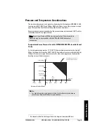
The relative lengths of the measurement section and active shield section can be
specified to suit a particular application. If the measured range will be short relative to
the total length of the electrode, specify a short measurement section. This increases the
achievable resolution of the measurement, since any change in level will be greater
relative to the length of the measurement section.
Measuring-
Circuit
Measuring-
Circuit
Conventional Capacitance
Measurement
SITRANS LC500 with
Active Shield
C1
C2
C3
R = (C1 + C2 + C3) + Ca
(C1 + C2 + C3) + Ca + Cm
R = Ca
Ca + Cm
Ca
Ca
Cm
Cm
R
= Ratio between initial
capacitance and total
capacitance
Ca = Initial capacitance (air)
Cm = Capacitance Increase
(product)
C1 =
Capacitance
connection
point
C2 = Capacitance connection
cable
C3 = Capacitance
Process
connection (includes active
part)
frequency (f)
K
capacitance (C)
active shield
active
measurement
section
probe seal
(inactive)
100%
0%
SITRANS
LC500
buffer
empty
tank
full
tank