7ML19985GE04
SITRANS LC500 – OPERATING INSTRUCTIONS
Page 75
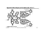
Appendix B
Appendix B: LCD
display examples
LCD: alphanumeric display
examples
Menu Item Indicator:
Menu Level Indicator:
Internal diagnostics detects anomaly:
Solid-state switch output closed when probe is
covered (displayed while button pressed):
Solid-state switch output open when probe is
covered (displayed while button pressed):
Solid-state switch output closed and probe
covered, = sign indicates current probe status
(displayed when button released):
Solid-state switch output disabled:
Solid-state switch output open when Fault
detected:
Solid-state switch output closed when Fault
detected:
Solid-state switch / current-loop output functions
due to Faults are disabled:
Current-loop, current goes to 22 mA when Fault
detected:
Current-loop, current goes to 3.6 mA when Fault
detected:
Current-loop, output in Analog (proportional)
mode:
Indicator for range operation, normal (URV > LRV):
Indicator for range operation, inverted (URV <
LRV):
Output out of limits, PV outside Variable Limits:
Indicator for Factory Set, all parameters are
original:
Indicator for Factory Set, range settings have
been changed:
Indicator for Factory Set, other settings have been
changed also:
Indicator for Factory Set, reset all variables back
to factory setting:
Function test indicator, all outputs in digital mode
invert their output status:
Transmitter variable selected for PV:
Keylock protection level:
Simulation is active. Transmitter Variable TVO
driven by simulation value:
M 00
SEL 1
FLt
S: oc
S: oo
S= oc
S: – –
F: oo
F: oc
F: – –
Hi
Lo
An
nor
inv
ooL
FAC A
FAC P
FAC?
do it
0 = /o
Pv=0
PL 0
SIM


