background image


Maintenance and service 


9.2 Firmware update 

SIRIUS 3RW50 soft starter 
Manual, 09/2019, A5E35628455002A/RS-AA/001 

187


Result 

You have performed a firmware update for the selected device. The selected device 

automatically restarts. 


Note 
Firmware update of the 3RW5 HMI High Feature 
Please note that the display switches off for about 30 seconds when the firmware is 

activated. 


Содержание SIRIUS 3RW50

Страница 1: ...ual 09 2019 A5E35628455002A RS AA 001 Description 1 Safety information 2 Mounting and dismantling 3 Connecting 4 Parameter assignment 5 Commissioning 6 Functions 7 Messages and diagnosis 8 Maintenance and service 9 Technical specifications 10 Dimension drawings 11 Circuit diagrams 12 Example circuits A Third party software B ...

Страница 2: ...may be operated only by personnel qualified for the specific task in accordance with the relevant documentation in particular its warning notices and safety instructions Qualified personnel are those who based on their training and experience are capable of identifying risks and avoiding potential hazards when working with these products systems Proper use of Siemens products Note the following WA...

Страница 3: ...s for 3RW50 soft starters 25 1 10 2 3RW5 communication module 27 1 10 3 SIRIUS Soft Starter ES TIA Portal 28 1 10 4 3RW5 HMI 30 1 11 Additional documentation 32 1 12 Siemens Industry Online Support 34 1 13 Support Request 37 2 Safety information 39 2 1 ESD Guidelines 39 2 2 Reactive power compensation 41 2 3 Five safety rules for working in or on electrical systems 42 2 4 Electromagnetic compatibi...

Страница 4: ...4 Mounting and dismantling box terminal blocks 76 4 5 Mounting terminal covers on main circuit connections 78 4 6 Connecting the control terminals screw terminals 79 4 7 Disconnecting the control current form the screw type terminals 80 4 8 Connecting the control terminals spring type terminals 81 4 9 Disconnecting the control current from the spring loaded terminals 82 4 10 Replacing the control ...

Страница 5: ...on 129 7 6 Soft torque 130 7 7 ATEX IECEx certified motor overload protection 133 7 8 Additional parameters 136 7 9 Test with small load 137 7 10 Control via digital input 139 7 11 3RW5 HMI Standard 141 7 11 1 Design of the Standard 3RW5 HMI 141 7 11 2 Standard 3RW5 HMI menu 143 7 11 3 Display of the error number with 3RW5 HMI Standard 145 7 12 3RW5 HMI High Feature 146 7 12 1 Monitoring 146 7 12 ...

Страница 6: ...nance and service 185 9 1 Maintenance and repairs 185 9 2 Firmware update 186 9 3 Performing firmware update with micro SD card 3RW5 HMI High Feature 188 9 4 Restoring factory setting 189 9 4 1 Effects of the factory setting 189 9 4 2 Restoring the factory settings via High Feature 3RW5 HMI 190 9 4 3 Restoring the factory settings with the Master RESET button via 3RW5 HMI High Feature 191 9 4 4 Re...

Страница 7: ...ting the temperature sensor 214 A 2 8 Connecting the evaluation unit to the analog output 215 A 3 Special applications 216 A 3 1 Wiring for ATEX IECEx applications with additional line contactor 216 A 3 2 Controlling a motor with a magnetic parking brake 218 A 3 3 EMERGENCY STOP shutdown to SIL 1 or PL c with a 3SK1 safety relay 219 A 3 4 EMERGENCY STOP shutdown to SIL 3 or PL e with a 3SK1 safety...

Страница 8: ...Table of contents SIRIUS 3RW50 soft starter 8 Manual 09 2019 A5E35628455002A RS AA 001 ...

Страница 9: ...d for everyone involved in the following tasks Planning and configuring systems Installation Commissioning Service and maintenance Requirements for use of 3RW5 soft starters Basic knowledge of the following areas General electrical engineering Drive technology Automation technology Handling the automation system and the software used ...

Страница 10: ...rminals inputs outputs Scale of the setting element Ie RESET TEST key Interface for 3RW5 HMI Standard accessories or 3RW5 HMI High Feature accessories Setting elements for parameter assignment MODE key Interface for 3RW5 communication module accessory Connectable conductor cross sections Diagnostics LEDs and RESET key Eye for lead seal Main circuit connection motor ...

Страница 11: ...100 of the line voltage t2 The internal bypass contacts close and the power semiconductors are bypassed The 3RW50 soft starter is in bypass operation Coast down to zero speed is activated when the switch on command is cancelled t4 and the motor is shut down The power semiconductors also ensure that the motor coasts down smoothly to a stop As long as the stopping time is active t4 to t5 energy is s...

Страница 12: ...nal 3RW5 HMI Standard or 3RW5 HMI High Feature Connection to motor in standard circuit Adjustable RESET MODE Manual RESET Remote RESET Auto RESET for the functions of motor protection Extended full motor protection via optional thermistor motor protection for connection of a temperature switch e g Thermoclick or a thermistor e g PTC type A alternative to analog output Optional analog output for di...

Страница 13: ...5 HMI Standard accessories 3RW5 HMI High Feature accessory firmware version V3 0 or higher PC with SIRIUS Soft Starter ES TIA Portal via local interface on 3RW5 HMI High Feature Fieldbus via optional communication module PC or programming device with configuration software of the controller e g STEP 7 Programmable logic controller e g SIMATIC S7 1500 PC with SIRIUS Soft Starter ES TIA Portal Premi...

Страница 14: ...l 1 Fieldbus via 3RW5 communication module via user program 3RW50 soft starter LEDs LEDs Via input IN Setting elements 1 Via the local interface on the 3RW5 HMI High Feature or via a 3RW5 communication module PROFINET or PROFIBUS 2 Analog output for device version with analog output only and ON RUN relay output can be set 3 Communication parameters of all compatible communication modules can be se...

Страница 15: ...only one control source can ever possess the master control function at one time different priorities are assigned to the modes Read access is also possible without master control function Control source Input IN operating mode Manual operation local input controlled Control source 3RW5 HMI operating mode Manual operation local HMI controlled Control source SIRIUS Soft Starter ES TIA Portal operat...

Страница 16: ...ol source is connected to the 3RW50 soft starter via the 3RW5 communication module In the operating mode manual bus the master control function rests with the SIRIUS Soft Starter ES TIA Portal Premium software Operating mode manual local In the operating mode manual local the master control function rests with a control source directly on the 3RW50 soft starter Input IN 3RW5 HMI accessories SIRIUS...

Страница 17: ...hes to Manual bus Connection abort Operating mode manual local The master control function switches to Manual local Input controlled Further information You will find more information on the 3RW5 communication modules in the manual for the 3RW5 communication module in question 1 5 2 Sets the operating mode Fundamental response when changing the mode A higher priority mode can take over as master c...

Страница 18: ...ing on the 3RW5 communication module the Automatic mode gives up the master control function to the Input IN Revocation of the master control by other control sources In the Automatic mode the master control function can be withdrawn from any control source Operating mode manual bus Assume master control SIRIUS Soft Starter ES TIA Portal Premium actively assumes the master control function from th...

Страница 19: ...unction is withdrawn from the Input IN as follows Action LOCAL REMOTE on the 3RW5 HMI Command in SIRIUS Soft Starter ES TIA Portal local interface on the 3RW5 HMI High Feature Manual operation local HMI controlled mode Assume master control The 3RW5 HMI actively assumes the master control function via the action LOCAL REMOTE from the lower priority control source If the master control function at ...

Страница 20: ...ely gives up the master control function to the Automatic mode or alternatively to the Input IN In the following cases the master control function is given up to the Input IN No 3RW5 communication module is connected to the 3RW50 soft starter The parameter Control via digital input Page 139 is set to Permanent activation Revocation of the master control by other control sources The master control ...

Страница 21: ...oft starter Manual 09 2019 A5E35628455002A RS AA 001 21 1 6 Device versions Size S6 Size S12 Size S6 Size S12 Ie Rated operational current P Rated power The stated power ratings apply to a rated operational voltage of Ue 400 V in a standard circuit ...

Страница 22: ...supply system which can have a negative influence on other devices Flicker in lights Influence on computer systems Contactors and relays dropping out The 3RW50 soft starter controls the voltage continuously The torque and the current are thus also increased continuously The power supply system is safeguarded against peak loads and the drive train is protected against damage Smooth starting stoppin...

Страница 23: ... The soft starter can be configured with the STS Simulation Tool for Soft Starters software The STS suggests suitable soft starters for the respective application based on the entered motor and load data and application requirements as well as providing information on the parameterization You can download the Simulation Tool for Soft Starters STS for free on the 3RW5 topic page https support indus...

Страница 24: ... table The following table shows the size and rated operational current for Ue 400 V and TU 40 C and in a standard circuit Rated operational current Ie of the soft starter Rated operational power Pe of the soft starter x x S6 Ie 143 A Pe 75 kW 5 5 Ie 171 A Pe 90 kW 5 6 S12 Ie 210 A Pe 110 kW 7 2 Ie 250 A Pe 132 kW 7 3 Ie 315 A Pe 160 kW 7 4 Ie 370 A Pe 200 kW 7 5 Ie 470 A Pe 250 kW 7 6 Ie 570 A Pe...

Страница 25: ...Description 1 10 Accessories SIRIUS 3RW50 soft starter Manual 09 2019 A5E35628455002A RS AA 001 25 1 10 Accessories 1 10 1 Accessories for 3RW50 soft starters ...

Страница 26: ...P 3RW5980 0CE00 Modbus RTU 3RW5980 0CR00 Modbus TCP 3RW5980 0CT00 firmware version V1 1 or higher Box terminal blocks Size S6 3RT1956 4G Size S12 3RT1966 4G Terminal covers for box terminals Size S6 3RT1956 4EA2 Size S12 3RT1966 4EA2 Terminal covers for cable lug connection and bar connection Size S6 3RT1956 4EA1 Size S12 3RT1966 4EA1 Fan cover Size S6 and S12 3RW5985 0FC00 Push in lugs for wall m...

Страница 27: ...et IP communication module 3RW5 Modbus RTU communication module 3RW5 communication module Modbus TCP firmware version V1 1 The following accessories are available for using the 3RW5 communication modules on the 3RW50 soft starter Push in lugs for wall mounting 3ZY1311 0AA00 COM connecting cable 3RW5900 0CC00 Integration into the automation software The 3RW50 soft starter can be integrated in an au...

Страница 28: ...oning operation and diagnostics of 3RW5 soft starters 3RW50 soft starters are supported depending on the firmware as of V15 1 Update 2 You connect your PC programming device to the soft starter via the local interface on the optional 3RW5 HMI High Feature By displaying all operating data service data and diagnostics data SIRIUS Soft Starter ES TIA Portal supplies reliable information helping to av...

Страница 29: ...tions x x Service data min max pointer statistic data x x Access via PROFIBUS PROFINET x Parameter comparison x Teleservice via MPI x Routing x 1 Typicals with Service Pack 1 and higher You can find further information on the SIRIUS Soft Starter ES TIA Portal software program and necessary versions and updates in the Catalog IC 10 https support industry siemens com cs ww en view 109747945 and on t...

Страница 30: ...r tests via the RESET TEST key Starting and stopping the motor via control keys Switching modes via the LOCAL REMOTE key Setting the PROFIBUS station address Display of the device LEDs of the 3RW5 HMI Standard shows the messages of the following devices 3RW50 soft starter 3RW5 HMI Standard Communication module if there is one 3RW5 HMI High Feature HF Note 3RW5 HMI High Feature The 3RW50 soft start...

Страница 31: ...les PROFINET device name and IP parameters PROFIBUS station address EtherNet IP IP parameters Modbus RTU station address Modbus TCP IP parameters Backup of parameterization data on a micro SD card The display of the device LEDs of the 3RW5 HMI High Feature shows the messages of the following devices 3RW50 soft starter 3RW5 HMI High Feature Communication module if there is one Firmware updates can ...

Страница 32: ...siemens com cs ww en view 109753752 Equipment Manuals for the 3RW5 soft starter https support industry siemens com cs ww en ps 16212 man Equipment Manual for the 3RW5 PROFINET communication modules https support industry siemens com cs ww en view 109753754 Equipment Manual for the 3RW5 PROFIBUS communication module https support industry siemens com cs ww en view 109753753 Equipment Manual for the...

Страница 33: ...q Downloads for soft starters 3RW5 https support industry siemens com cs ww en ps 16212 dl Catalog IC 10 https support industry siemens com cs ww en view 109747945 Product support for STEP 7 TIA Portal https support industry siemens com cs ww en ps 14672 Further information on PROFINET https www siemens com global en home products automation industrial communication profinet html Premium Efficienc...

Страница 34: ...s ww en Product support Here you will find all the information and comprehensive know how for your product FAQs Our replies to frequently asked questions Manuals operating instructions Read online or download available as PDF or individually configurable Certificates Clearly sorted according to approving authority type and country Characteristics For support in planning and configuring your system...

Страница 35: ...rectly to a specialist in Technical Support Notifications Make sure you always have the latest information individually tailored to your needs Filter Simple management and re use of your filter settings from Product Support and the Technical Forum Favorites Tagging Create your own knowledge database by assigning Favorites and Tags to documents simply and efficiently Entries last viewed Clear prese...

Страница 36: ...port app to access all the device specific information available on the Siemens Industry Online Support portal for a particular article number including operating instructions manuals datasheets FAQs etc The Siemens Industry Online Support app is available for iOS Android or Windows Phone devices You can download the app from the following links Link for Android Link for iOS Link for Windows Phone...

Страница 37: ...st Using the Support Request form in Online Support you can send your query directly to our Technical Assistance After describing your query in a few guided steps you will immediately be provided with possible suggestions for solving the problem Support Request Internet https support industry siemens com My ww en requests ...

Страница 38: ...Description 1 13 Support Request SIRIUS 3RW50 soft starter 38 Manual 09 2019 A5E35628455002A RS AA 001 ...

Страница 39: ...for such electrostatic sensitive components devices This is also the international abbreviation for such devices ESD devices are identified by the following symbol NOTICE Electrostatic discharge ESD devices can be destroyed by voltages well below the threshold of human perception These static voltages develop when you touch a component or electrical connection of a device without having drained th...

Страница 40: ...sures against electrostatic discharge Make sure the grounding is good When handling electrostatic sensitive devices ensure that your body the workplace and packaging are grounded In this way you can avoid becoming electrostatically charged Avoid direct contact As a general rule only touch electrostatic sensitive devices when this is unavoidable e g during maintenance work Handle the devices withou...

Страница 41: ...ft starter will be damaged Active filters e g for reactive power compensation must not be operated parallel to the motor control device If capacitors are to be used to correct the power factor actively or passively they must be connected on the line side of the device They must not actively control the power factor during the starting and coasting down phases If a contactor disconnector or main co...

Страница 42: ...all pole disconnection of live parts All pole disconnection can be achieved e g by Switching off the miniature circuit breaker Switching off the motor circuit breaker Unscrewing fusible links Removing LV HRC fuses 2 The feeder must be locked against inadvertent reconnection to ensure that it remains isolated for the duration of the work This can be achieved for instance by locking the motor and sy...

Страница 43: ...soft starter Manual 09 2019 A5E35628455002A RS AA 001 43 2 4 Electromagnetic compatibility EMC according to IEC 60947 4 1 This product is designed for Environment A It may produce radio interference in domestic environments in which case the user may be required to take adequate mitigation measures ...

Страница 44: ...es and components should only be connected to an enterprise network or the internet if and to the extent such a connection is necessary and only when appropriate security measures e g firewalls and or network segmentation are in place For additional information on industrial security measures that may be implemented please visit https www siemens com industrialsecurity Siemens products and solutio...

Страница 45: ...for operation in a temperature range of 25 C to 60 C In ambient temperatures higher than 40 C take the derating of the rated operational current into consideration You can find further information on derating in the Technical specifications Page 193 in the section Power electronics or in Catalog IC 10 https support industry siemens com cs ww en view 109747945 Note Temperature sensor For ATEX IECEx...

Страница 46: ...Parameterizing the motor protection functions RESET setting Note that the Auto RESET setting is not permissible when operating motors in hazardous areas Short circuit protection The 3RW50 soft starter does not have short circuit protection Make sure that short circuit protection is provided Line protection Avoid impermissibly high cable surface temperatures by correctly dimensioning the cross sect...

Страница 47: ...ully observe the following standards IEC EN 60079 14 VDE 0165 1 For electrical apparatus for hazardous areas IEC EN 60079 17 Inspection and maintenance of electrical installations in explosive atmosphere EN 50495 Safety devices required for the safe functioning of equipment with respect to explosion risks ATEX IECEx specific safety data The motor protection function according to ATEX IECEx for 3RW...

Страница 48: ...al 09 2019 A5E35628455002A RS AA 001 2 7 Protection against unauthorized actuation Protect freely accessible operator controls on your machine system against unauthorized actuation if this could result in a risk or danger Take suitable action in this regard for example a lockable key operated switch ...

Страница 49: ...628455002A RS AA 001 49 2 8 Recycling and disposal For environmentally friendly recycling and disposal of your old device please contact a company certified for the disposal of old electrical and or electronic devices and dispose of the device in accordance with the regulations in your country ...

Страница 50: ...Safety information 2 8 Recycling and disposal SIRIUS 3RW50 soft starter 50 Manual 09 2019 A5E35628455002A RS AA 001 ...

Страница 51: ...ionally secure the 3RW5 HMI Standard or High Feature in the cabinet door or on a level surface Connect the HMI connecting cable to the 3RW50 soft starter Page 55 Installing the Standard 3RW5 HMI into the control cabinet door Page 56 Installing the High Feature 3RW5 HMI in the control cabinet door Page 58 Installing the Standard 3RW5 HMI on a flat surface Page 62 Installing the High Feature 3RW5 HM...

Страница 52: ...Size Article number of the soft starter Article number of the fan cover S6 3RW505 3RW5985 0FC00 S12 3RW507 Procedure NOTICE Material damage due to mechanical load Avoid a mechanical load on the fan hub when mounting the fan cover Place the fan cover on the fan and fasten the fan cover using the 4 screws supplied Result The fan cover provides enhanced touch protection and prevents the fan from bein...

Страница 53: ...t Level surface e g sufficiently strong mounting plate 4 properly executed drill holes with thread or plug on the level surface 4 screws of suitable size and with regular thread for insertion into the selected mounting plate or wall Use an additional four washers if the head of the screw is smaller than the specified diameter Screwdriver depending on the drive of the screws If necessary use shims ...

Страница 54: ...ransport install and dismantle a heavy device Use suitable lifting equipment and wear personnel protective equipment Screw the lower 2 screws into the mounting plate Ensure that both screws protrude a minimum of 1 5 cm min 2 cm for size 4 and then place the 3RW50 soft starter onto the 2 lowermost screws from above Tilt the 3RW50 soft starter up so that it is resting level against the mounting plat...

Страница 55: ...t HMI connecting cable accessory of suitable length Removed hinged cover Page 65 Procedure Connect the HMI connecting cable to the 3RW50 soft starter Observe the coding of the plug and socket Lock the connector in the socket Route the HMI connecting cable downward out of the HMI cable duct Then fit the hinged cover Page 65 Make sure that you install the cable in accordance with EMC requirements Fo...

Страница 56: ...er Page 55 Cutout of suitable size in the control cabinet door Device depth of the 3RW5 HMI Standard Total depth 32 mm Embedded depth 29 mm Permissible wall thickness of the cabinet door Without IP65 door mounting kit 1 5 to 3 0 mm With IP65 door mounting kit 1 0 to 7 0 mm For using door mounting kit IP65 IP65 door mounting kit accessory The fixing brackets with marking 001 are intended for a 3RW5...

Страница 57: ...n the rear side of the 3RW5 HMI Standard Ensure that the seal does not overlap Place the 3RW5 HMI Standard in the cutout of the control cabinet door Continue to screw the screws into the fixing brackets until they protrude approx 10 mm at the front Fasten the fixing brackets onto the 3RW5 HMI Standard Tighten the 3RW5 HMI Standard with a tightening torque of 0 3 0 35 Nm Ensure that all of the scre...

Страница 58: ...rface area 3 4 3 Installing the High Feature 3RW5 HMI in the control cabinet door Requirements Note the mounting positions minimum clearances and ambient conditions stated on the data sheet 3RW5 HMI High Feature accessories HMI connecting cable accessory of suitable length connected to the soft starter Page 55 Cutout of suitable size in the control cabinet door Device depth of the High Feature 3RW...

Страница 59: ...IRIUS 3RW50 soft starter Manual 09 2019 A5E35628455002A RS AA 001 59 Procedure without door mounting kit IP65 Place the 3RW5 HMI High Feature in the cutout of the control cabinet door Ensure that the 3RW5 HMI High Feature engages audibly in the 4 fixtures ...

Страница 60: ...E35628455002A RS AA 001 Procedure with door mounting kit IP65 Remove the protective film from the adhesive tape on the seal and secure the seal on the rear side of the 3RW5 HMI High Feature Ensure that the seal does not overlap Place the 3RW5 HMI High Feature in the cutout of the control cabinet door ...

Страница 61: ...ning torque of 0 3 0 35 Nm Ensure that all of the screw heads are in contact with the fixing bracket Procedure for connecting with the HMI connecting cable Observe the coding of the plug and socket Lock the connector in the socket The HMI connecting cable in the cable duct of the 3RW5 HMI High Feature may only be routed downward Make sure that you install the cable in accordance with EMC requireme...

Страница 62: ...to the drilling pattern Page 196 2 head screws M4 x 12 DIN ISO 7045 to fit the drill holes Screwdriver depending on the drive of the screws 2 push in lugs accessories for wall mounting HMI connecting cable accessory of suitable length connected to the soft starter Page 55 Procedure Observe the coding of the plug and socket Lock the connector in the socket The HMI connecting cable in the cable duct...

Страница 63: ...3 4 5 Installing the High Feature 3RW5 HMI on a flat surface Requirements Note the mounting positions minimum clearances and ambient conditions stated on the data sheet 3RW5 HMI High Feature accessories Level surface e g sufficiently strong mounting plate 2 properly executed drill holes with thread or plugs on the level surface Refer to the drilling pattern Page 197 2 head screws M4 x 12 DIN ISO 7...

Страница 64: ...onnecting cable in the cable duct of the 3RW5 HMI High Feature may only be routed downward Make sure that you install the cable in accordance with EMC requirements For example route data cables separately from the motor cable Connect both sides of shielded cables over a large surface area Insert the push in lugs into each side of the enclosure until you hear them engage and fix the 3RW5 HMI High F...

Страница 65: ... hinged cover of the 3RW50 soft starter Requirements Hinged cover Procedure Unlock the hinged cover on both sides Open the hinged cover at an angle of approx 20 Loosen the hinges horizontally to the soft starter surface starting from the left Take the cover off the 3RW50 soft starter Follow the steps in reverse order to install the replacement hinged cover ...

Страница 66: ...ng positions minimum clearances and ambient conditions stated on the data sheet 2 properly executed drill holes with thread or plugs on the level surface The 3RW5 communication module must be mounted to the left of the 3RW50 soft starter Observe the position of the 3RW5 communication module in the drilling pattern Page 198 The COM connecting cable has a limited length 2 head screws M4 x 12 DIN ISO...

Страница 67: ... the head screws 3 Attach the 3RW5 communication module on the bottom and top side of the level surface using the head screws Result You have mounted the 3RW5 communication module on a level surface You can connect the COM connecting cable to the 3RW50 soft starter Page 85 and on the 3RW5 communication module Page 86 and connect the 3RW50 soft starter to the fieldbus via the 3RW5 communication mod...

Страница 68: ...u can find further information on connecting to the fieldbus in the Equipment Manual for the respective 3RW5 communication module Removed COM connecting cable Page 88 Screwdriver depending on the drive of the screws Procedure Illustration similar 1 Loosen the head screws on the 3RW5 communication module 2 Pull out the push in lugs from the 3RW5 communication module Result You have removed the 3RW5...

Страница 69: ...SIRIUS 3RW50 soft starter Manual 09 2019 A5E35628455002A RS AA 001 69 Connecting 4 4 1 Connections 4 1 1 Overview of all connections ...

Страница 70: ...sensor optional T11 T21 T22 Connection for Thermoclick T11 T21 T12 Connection for PTC Type A Analog output AQ AQ I and AQ U Connection of an evaluation unit to display the motor current optional average phase current in AQ AQ U For evaluation units with output signal type Voltage Signal range 0 10 V AQ AQ I For evaluation units with output signal type Current Signal range 4 20 mA factory setting M...

Страница 71: ...Connecting 4 1 Connections SIRIUS 3RW50 soft starter Manual 09 2019 A5E35628455002A RS AA 001 71 4 1 2 State diagrams of the inputs and outputs ...

Страница 72: ...ork 1 L1 3 L2 5 L3 Input IN to switch the motor on and off Main circuit connection load motor 2 T1 4 T2 6 T3 Output 13 14 Parameterized to signal operating state ON Output 13 14 Parameterized to signal operating state RUN Output 23 24 To signal operating state BYPASSED Output 95 96 NC to signal warnings and faults Output 95 98 NO to signal warnings and faults Temperature sensor Thermoclick ...

Страница 73: ...zes S6 and S12 Terminal cover for box terminal in sizes S6 and S12 Procedure DANGER Hazardous voltage Will cause death or serious injury Turn off and lock out all power supplying this device before working on this device 1 Connect the main circuit connections line side motor side of the 3RW50 soft starter Page 74 2 Optionally install the box terminal blocks for sizes S6 and S12 Page 76 3 Optionall...

Страница 74: ...n the front beneath the hinged cover Pay attention to the required tools indicated on the front beneath the hinged cover Size Article number Tightening torque S6 3RW505 10 14 Nm S12 3RW507 14 24 Nm Procedure DANGER Hazardous voltage Will cause death or serious injury Turn off and lock out all power supplying this device before working on this device Pay attention to the diagram on the packaging of...

Страница 75: ...onnection mains motor SIRIUS 3RW50 soft starter Manual 09 2019 A5E35628455002A RS AA 001 75 Example circuits Feeder assembly type of coordination 1 fuseless Page 203 Feeder assembly type of coordination 1 with fuses Page 204 Feeder assembly type of coordination 2 Page 205 ...

Страница 76: ...4 Mounting and dismantling box terminal blocks Requirements Box terminal blocks accessories for 3RW50 soft starters Pay attention to the required tools indicated on the front beneath the hinged cover Assembly procedure Plug the new box terminal blocks into the main circuit connections and tighten the screws with a torque of 4 5 6 Nm ...

Страница 77: ...ng procedure DANGER Hazardous voltage Will cause death or serious injury Turn off and lock out all power supplying this device before working on this device Unscrew the 3 screws on each of the box terminal blocks and lever the box terminal blocks off the main circuit connections Pull the box terminal blocks off the main circuit connections ...

Страница 78: ...ssory for 3RW50 soft starter Note Touch protection by terminal cover Touch protection according to EN 50274 finger safe only for vertical contact from the front Procedure DANGER Hazardous voltage Will cause death or serious injury Turn off and lock out all power supplying this device before working on this device Make sure that you mount the terminal cover the right way round on the connecting ter...

Страница 79: ...required tools indicated on the front beneath the hinged cover Procedure DANGER Hazardous voltage Will cause death or serious injury Turn off and lock out all power supplying this device before working on this device Example circuits Control by pushbutton Page 206 Control by switch Page 207 Switching with the control supply voltage Page 208 Control by PLC Page 210 Actuation of a line contactor Pag...

Страница 80: ...5002A RS AA 001 4 7 Disconnecting the control current form the screw type terminals Requirements Pay attention to the required tools indicated on the front beneath the hinged cover Procedure DANGER Hazardous voltage Will cause death or serious injury Turn off and lock out all power supplying this device before working on this device ...

Страница 81: ...o the required tools indicated on the front beneath the hinged cover Procedure DANGER Hazardous voltage Will cause death or serious injury Turn off and lock out all power supplying this device before working on this device Example circuits Control by pushbutton Page 206 Control by switch Page 207 Switching with the control supply voltage Page 208 Control by PLC Page 210 Actuation of a line contact...

Страница 82: ...5002A RS AA 001 4 9 Disconnecting the control current from the spring loaded terminals Requirements Pay attention to the required tools indicated on the front beneath the hinged cover Procedure DANGER Hazardous voltage Will cause death or serious injury Turn off and lock out all power supplying this device before working on this device ...

Страница 83: ...control terminals Requirements Control terminal as spare part screw terminal 3RW5980 1TR00 spring type 3RW5980 2TR00 Dismantling procedure DANGER Hazardous voltage Will cause death or serious injury Turn off and lock out all power supplying this device before working on this device Press against the lock and pull the control terminal out ...

Страница 84: ...g 4 10 Replacing the control terminals SIRIUS 3RW50 soft starter 84 Manual 09 2019 A5E35628455002A RS AA 001 Assembly procedure Place the control terminal onto the intended connection until the terminal engages ...

Страница 85: ...ting cable accessory Procedure Illustration similar 1 Plug the bus connector of the COM connecting cable without pin connectors into the corresponding socket on the 3RW50 soft starter Observe the coding of the bus connector and of the socket 2 Lock the bus connector in the socket 3 Install the hinged cover Page 65 Result You have connected the COM connecting cable to the 3RW50 soft starter You can...

Страница 86: ...ver cap and keep the cover cap in a safe place 3RW50 soft starter with connected COM connecting cable accessory Page 85 NOTICE Damage to property due to electrical voltage Switch off the power to the 3RW5 soft starter before starting work main and control supply voltage Procedure NOTICE Material damage due to incorrect plug in connection Use the front plug in connection of the 3RW5 communication m...

Страница 87: ...ble latches into place Route the COM connecting cable in front under the 3RW50 soft starter and then on the side next to the 3RW50 soft starter Maintain sufficient distance from the main power connections and ensure that your routing is EMC compliant Result The 3RW5 communication module is now properly mounted and connected to the 3RW50 soft starter You can connect the 3RW50 soft starter via the 3...

Страница 88: ...NOTICE Damage to property due to electrical voltage Switch off the power to the 3RW5 soft starter before starting work main and control supply voltage Procedure Illustration similar 1 Loosen die securing mechanism on the bus connector of the COM connecting cable 2 Pull the bus connector of the COM connecting cable out of the plug in connection of the 3RW5 communication module for the 3RW5 soft sta...

Страница 89: ...d hinged cover Page 65 COM connecting cable accessory on the 3RW5 communication module removed Page 88 Procedure Illustration similar 1 Loosen die securing mechanism on the bus connector of the COM connecting cable 2 Pull the bus connector of the COM connecting cable out of the socket on the 3RW50 soft starter 3 Install the hinged cover Page 65 Result You have disconnected the COM connecting cable...

Страница 90: ...Connecting 4 11 COM connection cable SIRIUS 3RW50 soft starter 90 Manual 09 2019 A5E35628455002A RS AA 001 ...

Страница 91: ...of Soft Torque Parameterization of ON RUN relay output Parameterizing mode Restoring factory setting RESET TEST key Acknowledges faults Performing the self test user test Parameterization of ON RUN relay output Parameterizing mode Restoring factory setting CLASS setting for the motor overload protection Rated operational current Ie of the motor Current limiting factor as a multiple of the set rate...

Страница 92: ...ys on the setting elements are approximate values which are subject to production engineering tolerances To perform a detailed setting a 3RW5 HMI should be used Display of the parameter value in the 3RW5 HMI accessories 3RW5 HMI Standard During the setting of parameters at the setting elements the current value is indicated on the display of the 3RW5 HMI Standard and undergoes cyclic updating 3RW5...

Страница 93: ...ting corresponds to 7 times the maximum rated operating current Ie of the 3RW50 soft starter 4 x Ie Ramp up time 0 20 s If parameter value 0 is set the motor is switched on with a ramp up time of approx 100 ms 10 s Starting voltage 30 100 30 Stopping time 0 20 s 0 s Soft torque Off LED off On LED on Off RESET MODE Manual RESET LED off Remote RESET LED flashes green Auto RESET LED lit green Manual ...

Страница 94: ...e s Current limitation Stopping time s Conveyor belt full 70 5 7 Ie 10 Roller conveyor full 60 5 7 Ie 10 Compressor without pressure 50 4 4 Ie Not relevant Small fan 40 2 4 Ie Not relevant Pump1 40 3 4 Ie 10 Hydraulic pump 40 2 4 Ie Not relevant Agitator 40 2 4 Ie Not relevant Milling machine 40 4 4 Ie Not relevant 1 It is recommended that the Soft Torque function is activated ...

Страница 95: ...S and Ie ein Page 126 The scale for rated operational current Ie is listed for each type of connection in the table on the front of the 3RW50 soft starter Make sure that the arrow of the CLASS setting element points to the required setting 3 Set the soft starting on the setting elements t and U Page 119 4 Set the current limit at the setting element Current limiting value x Ie Page 123 5 Set the s...

Страница 96: ...ft Torque at the same time Procedure WARNING Automatic restart Can cause death or serious injury If a starting command is pending a restart will be triggered automatically after the reset This particularly applies if the motor protection has tripped Dangerous states of the system can result Reset the start command e g via the PLC or switch before performing a reset To do this for example link the ...

Страница 97: ...more information in Chapter Faults and remedial actions of the 3RW50 soft starter Page 168 with the comment Depends on parameter RESET MODE Note ATEX IECEx applications Note that the Auto RESET setting is not permissible when operating motors in hazardous areas RESET MODE LED Set RESET MODE Off Manual RESET Flashes green Remote RESET Lights up green Auto RESET Soft torque For more information see ...

Страница 98: ...T setting is not permissible when operating motors in hazardous areas Manual RESET Manual RESET means that the following options are available for acknowledging faults RESET TEST key on the 3RW50 soft starter RESET TEST key on the 3RW5 HMI Standard Reset via bus interface Reset via F key on 3RW5 HMI High Feature Reset via 3RW5 HMI High Feature diagnosis state Remote RESET Remote RESET means that f...

Страница 99: ...ntrol Use the Output function RUN in order for instance to control a line contactor connected upstream Requirements Control supply voltage is connected The 3RW50 soft starter does not signal any errors the STATE OVERLOAD LED is extinguished Procedure 1 Start programming by pressing the MODE key longer than 2 seconds until the STATE OVERLOAD LED flickers green Press and hold the MODE key 2 Also pre...

Страница 100: ...n switch between the modes at the output as often as you want Note If you do not press a key in the programming mode for longer than 10 s the 3RW50 soft starter automatically terminates the programming mode 5 Terminate programming mode by pressing the RESET TEST key for longer than 1 s until the STATE OVERLOAD LED no longer shines red Tip Alternatively output 13 14 may also be set in the Parameter...

Страница 101: ...E OVERLOAD LED flickers green and press and hold the MODE key 2 Switch off the supply voltage of the 3RW50 soft starter for at least 5 s After the 5 s elapse you can release the MODE key 3 Press and hold the MODE and TEST RESET keys 4 Switch the supply voltage of the 3RW50 soft starter on again When the SOFT TORQUE and RESET MODE LEDs flicker green the parameterization mode is active You can relea...

Страница 102: ...RLOAD Set parameter Off No selection Lights up green Control via digital input Lights up red Output ON RUN 2 Change the setting of the selected parameter using the RESET TEST key You can recognize your selection by the color combination of the three LEDs RN ER and MT Setting the parameter Control via digital input selection in Step 1 Control via digital input RN LED ER LED MT LED Set parameter val...

Страница 103: ...Off Lights up yellow Output function RUN 3 Switch off the supply voltage of the 3RW50 soft starter for at least 5 s The set parameters and parameter values are stored 4 Switch the supply voltage of the 3RW50 soft starter on again The set parameters and parameter values are now active Result You have set the parameters in the parameterizing mode Further information For more information about the pa...

Страница 104: ...the High Feature 3RW5 HMI Display Device LEDs Page 163 Navigation keys Cable duct Plug in connection for HMI connecting cable Master RESET key OK key ESC key Motor stop key Motor start key Favorites key Eyes for lead seals Hole for mounting the interface cover Status LED Page 166 Local interface point to point connection between PC and 3RW5 HMI High Feature Slot for micro SD card Page 157 ...

Страница 105: ...input field Switch between the measured values phase currents and phase currents eff For more information see Chapter Graphic display of measured values on the 3RW5 HMI High Feature Page 147 Jump to next menu item Set number or letter Jump to previous menu item Set number or letter To confirm To open the menu Jump to selected menu item To exit the menu Motor stops as parameterized if the 3RW5 HMI ...

Страница 106: ...igh Feature SIRIUS 3RW50 soft starter 106 Manual 09 2019 A5E35628455002A RS AA 001 5 10 Menu of the 3RW5 HMI High Feature Overview of the main menu options on the 3RW5 HMI High Feature Monitoring Diagnostics Parameter Overview Security Micro SD card ...

Страница 107: ...Parameter assignment 5 10 Menu of the 3RW5 HMI High Feature SIRIUS 3RW50 soft starter Manual 09 2019 A5E35628455002A RS AA 001 107 Menu of the 3RW5 HMI High Feature ...

Страница 108: ...Parameter assignment 5 10 Menu of the 3RW5 HMI High Feature SIRIUS 3RW50 soft starter 108 Manual 09 2019 A5E35628455002A RS AA 001 ...

Страница 109: ...Parameter assignment 5 10 Menu of the 3RW5 HMI High Feature SIRIUS 3RW50 soft starter Manual 09 2019 A5E35628455002A RS AA 001 109 ...

Страница 110: ...Parameter assignment 5 10 Menu of the 3RW5 HMI High Feature SIRIUS 3RW50 soft starter 110 Manual 09 2019 A5E35628455002A RS AA 001 ...

Страница 111: ... High Feature Menu Parameters Soft Starter Analog output Access protection to the 3RW5 HMI High Feature is not active or has been reset Device version with analog output Evaluation unit is connected properly Page 215 Parameter Parameter Description Output signal type Via the Output signal type parameter you can define with what type of signal the analog value will be output Deactivated 4 20 mA fac...

Страница 112: ...with 50 start value and the right stop with 200 end value You can divide the scale of the pointer instrument between the left stop and the right stop depending on the desired resolution The following parameters are given as examples at this point Output signal type 4 20 mA Range start value desired start value factor of the measured value Range end value desired end value factor of the measured va...

Страница 113: ...ipment Manual of the respective 3RW5 communication module Parameter Parameter Description Local interface activated via 3RW5 HMI High Feature only The parameter is only visible if the local interface is enabled factory setting Disables the local interface of the 3RW5 HMI High Feature Before you can connect a PC with SIRIUS Soft Starter ES TIA Portal to the 3RW50 soft starter via the local interfac...

Страница 114: ...y of the 3RW5 HMI High Feature as soon as they occur Error Enable factory setting Disable Warnings Enable factory setting Disable Operation display Up to 5 different measured values can be selected from a list of measured values These measured values are then shown in the status display You can find more information on input actions in Chapter Monitoring the measured values of the 3RW50 soft start...

Страница 115: ...eterize the 3RW50 soft starter according to the application with the setting suggestions Page 95 If necessary optimize the setting suggestions step by step Page 94 For example you can continually adjust the current limiting factor while the motor is starting up 4 Perform the self test user test Page 179 5 Optionally seal the 3RW50 soft starter with a lead seal Page 116 Result The 3RW50 soft starte...

Страница 116: ...g the hinged cover you protect the operator controls of the 3RW50 soft starter from unauthorized access It is nevertheless still possible to operate a 3RW5 HMI and acknowledge messages Tip The local interface and the memory module interface of the 3RW5 HMI High Feature can be protected from unauthorized access by sealing the interface cover Proceed in the same sequence as for sealing the hinged co...

Страница 117: ...ature 3RW5 HMI Requirements Control supply voltage is connected for the first time or the factory settings have been restored on the 3RW5 HMI High Feature Procedure Set the desired language Result The 3RW5 HMI High Feature is ready to use It is now possible to modify the parameters of the 3RW5 HMI High Feature the 3RW50 soft starter and any connected 3RW5 communication module ...

Страница 118: ...Commissioning 6 3 First commissioning of the High Feature 3RW5 HMI SIRIUS 3RW50 soft starter 118 Manual 09 2019 A5E35628455002A RS AA 001 ...

Страница 119: ...ltage from a parameterizable starting voltage to the line voltage within a definable ramp up time Application Systems in which a startup of the drive without interfering jerky movements is required E g pumps or small fans Voltage characteristic Voltage ramp with short ramp up time t1 Voltage ramp with long ramp up time t2 UN Line voltage US Parameterizable starting voltage t1 Short ramp up time t2...

Страница 120: ...al 09 2019 A5E35628455002A RS AA 001 Torque curve Torque with direct on line starting without 3RW50 soft starter Torque with short ramp up time Torque with long ramp up time Torque of the load Acceleration torque Difference of activation torque and torque of load ...

Страница 121: ...S AA 001 121 Current path Current characteristic with direct on line starting without 3RW50 soft starter Current characteristic with short ramp up time Current characteristic with long ramp up time Ie Rated operational current during rated operation ne Rated operating speed of the motor ...

Страница 122: ...torque which drives the load during the ramp up operation A longer ramp up time results in a shorter acceleration torque across the motor ramp up time The motor therefore runs up more slowly and smoothly Set the length of the ramp up time so that the motor can reach its rated speed by the time the end of the ramp up reached The actual motor starting time is load dependent and can differ from the p...

Страница 123: ...p If the current exceeds the parameterized current limit x Ie the voltage ramp function is aborted and the current limitation function starts The current limitation function remains active until the 3RW50 soft starter has detected the motor ramp up and the motor is in a normal operating state Application Avoiding current surges Reducing energy costs Current path Current characteristic with direct ...

Страница 124: ...ameterizable ramp up time The maximum possible current limiting value for the 3RW50 soft starter max position is 7x the value of the maximum rated operational current for the 3RW50 soft starter where this value is identical to 7x the value of the maximum rated operational current Ie which can be set This value is independent of the actual rated operational current Ie of the motor set at the 3RW50 ...

Страница 125: ...ives that abruptly come to a stop when switched off thereby damaging the transported goods E g bottle filling plants Voltage characteristic t1 t2 Stopping time UN Line voltage Parameter Parameter Description Stopping time The length of the stopping time defines the time within which the motor voltage is reduced from line voltage to 0 V It may take longer for the motor to actually coast down to a s...

Страница 126: ...overloaded or is functioning in the normal operating range When overload is detected the 3RW50 soft starter shuts the motor down The setting for RESET MODE determines how the motor is restarted Parameter WARNING Automatic restart following fault acknowledgement restart Can cause death or serious injury The 3RW50 soft starter immediately continues to operate with the values specified by the control...

Страница 127: ...ping class Rated operational current Ie The rated operational current Ie is the current that can be continuously conducted by the feeder switchgear and motor Normally this is the rated operational current Ie of the motor Recovery time following motor overload protection tripping The recovery time after the electronic overload protection is tripped is 5 minutes With Auto RESET set the error is auto...

Страница 128: ...0 soft starter recognizes this and reacts accordingly Two different types of measuring sensor can be connected to the 3RW50 soft starter PTC thermistors type A This sensor type is a temperature dependent resistor Thermoclick This sensor type is a temperature dependent switch Note ATEX IECEx certified motor overload protection Note that the sensor type Thermoclick is not permissible when operating ...

Страница 129: ...erty damage due to short circuits The intrinsic device protection system does not protect against irreparable equipment damage caused by short circuits Connect semiconductor fuses upstream in order to protect the power semiconductors against irreparable damage by short circuits e g in case of cable damage or an interturn fault in the motor Recovery time after device protection is triggered If the ...

Страница 130: ...oft Torque function reduces the drive acceleration rate shortly before the motor reaches its rated operating speed This produces an almost linear speed curve This helps to ensure smooth movement of a conveyor belt for example and so prevent fragile goods on the belt from tipping over Torque curve Torque with direct start Torque without Soft Torque Torque with Soft Torque ...

Страница 131: ...rinciple of operation of Soft Torque during stopping The Soft Torque function enables the motor to coast down smoothly at an almost constant rate of deceleration Ensuring that the motor coasts down smoothly is particularly useful for stopping pumps in order to prevent water hammers in the connected piping The Soft Torque function for stopping can only be activated when a stopping time of more than...

Страница 132: ...ctions 7 6 Soft torque SIRIUS 3RW50 soft starter 132 Manual 09 2019 A5E35628455002A RS AA 001 Speed curve ne Rated operating speed of the motor Motor speed with Soft Torque Motor speed without Soft Torque ...

Страница 133: ... PTC type A sensor only is approved Note Simulation Tool for Soft Starters Note that the Simulation Tool for Soft Starters Page 23 already takes into account the derating for certain ambient temperatures when selecting a suitable 3RW5 soft starter Parameterizing the soft starter The parameters for ATEX IECEx applications are to be set using the setting elements of the 3RW50 soft starter Setting th...

Страница 134: ...he 3RW5 HMI High Feature to ensure that the correct 3RW50 soft starter is tested Only in this way can the certified motor overload protection according to ATEX IECEx be guaranteed On soft starters in ATEX IECEx applications perform the Self test user test Page 179 during commissioning and periodically at intervals of no more than 36 months Certification of the 3RW50 soft starters The motor overloa...

Страница 135: ...h respect to explosion risks ATEX IECEx specific safety data The motor protection function according to ATEX IECEx for 3RW50 soft starters has the following safety data Safety Integrity Level SILCL 1 Hardware Fault Tolerance HFT 0 Interval for testing the protective functions 3 years Probability of failure on demand PFD 8x10 3 Probability of a dangerous failure per hour PFH 5x10 7 1 h Maintenance ...

Страница 136: ...perature by means of 3RW5 HMI High Feature only The 3RW50 soft starter is set to the typical ambient temperature actually prevailing in the plant Ensure that the set typical ambient temperature is not exceeded 40 C 50 C 60 C factory setting Test with small load The control and main circuit wiring is tested on a small load using a test motor A direction of rotation test can be performed by monitori...

Страница 137: ...ng of the control and main circuit to be checked with the aid of a small motor test motor In the test mode function Test with small load the motor operating states and all functions and messages can be executed and displayed by the 3RW50 soft starter as in normal operation If during an active Test with small load the 3RW50 soft starter detects a lack of main current a fault is generated with a shu...

Страница 138: ...nterface on the 3RW5 HMI High Feature With a fieldbus via a 3RW5 communication module only via a 3RW5 PROFINET or PROFIBUS communication module With SIRIUS Soft Starter ES TIA Portal Premium Configuration software of the control system e g STEP 7 with corresponding HSP User program Parameter Parameter Description Activate test with small load The 3RW50 soft starter switches to the test mode functi...

Страница 139: ...RW5 HMI High Feature Access protection to 3RW5 HMI High Feature is not active or has been reset Menu Parameters Soft Starter Additional parameters Control via digital input Parameter Parameter Description Control via digital input Manual activation On failure of the bus connection or a CPU stop the 3RW50 soft starter remains in the Automatic mode or the 3RW50 soft starter switches to the Automatic...

Страница 140: ... HMI or SIRIUS Soft Starter ES TIA Portal over the local interface on the 3RW5 HMI High Feature Page 17 Change the setting of the parameter Control via digital input in the parameterizing mode by means of a key combination on the 3RW50 soft starter Page 101 Remove the COM connecting cable from the 3RW5 communication module Page 88 Then restore the 3RW50 soft starter on the device to the factory se...

Страница 141: ...2019 A5E35628455002A RS AA 001 141 7 11 3RW5 HMI Standard 7 11 1 Design of the Standard 3RW5 HMI Display Navigation keys RESET TEST Status LED Page 165 Device LEDs Page 165 Plug in connection for HMI connecting cable Locking switch Cable duct Start key Stop key LOCL REMT ...

Страница 142: ...ard is the master control Changes master control LOCL means that the 3RW5 HMI Standard is the master control REMT means that the 3RW5 HMI Standard is not the master control Locking switch Locked Unlocked To be able to operate the 3RW50 soft starter with the Standard 3RW5 HMI the locking switch on the rear of the Standard 3RW5 HMI must be unlocked If the locking switch on the rear of the 3RW5 HMI S...

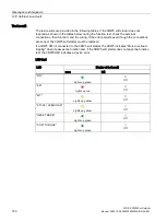
Страница 143: ...display OVLD OVERLOAD WN I OVLD The motor is switched on A motor overload protection warning is pending WN O OVLD The motor is switched off A motor overload protection warning is pending ER O OVLD The motor is switched off There is a fault at the motor overload protection OVLD No motor overload exists OVLD OVERLOAD in percent OVLD Status of the electronic motor overload protection as a percentage ...

Страница 144: ...nts is displayed in amps A I L1 Current measured value phase L1 is displayed in amps A I L2 Current measured value phase L2 is displayed in amps A I L3 Current measured value phase L3 is displayed in amps Parameter list Display Explanation xIe Current limiting value as a multiple of the set rated operational current Ie of the motor U ON Starting voltage s t ON Ramp up time s t OFF Stopping time CL...

Страница 145: ...r with 3RW5 HMI Standard The 3RW5 HMI Standard can display up to 10 active errors ER 0 9 in the menu item ERROR Procedure 1 Select the menu item ERROR 2 Press and hold a navigation key until the entry ER 0 appears on the display 3 Select the desired entry ER 0 9 using the navigation key If an entry contains an active error the associated error number Page 168 will appear above it If an entry conta...

Страница 146: ...er Graphic display of measured values on the 3RW5 HMI High Feature Page 147 Phase currents rms The phase currents are displayed in amperes You can monitor each phase L1 L2 L3 individually or the average of all 3 phases These measured values can be presented graphically as bar or line graph on the display of the 3RW5 HMI High Feature For more information see Chapter Graphic display of measured valu...

Страница 147: ...supports the graphic display of the measured values Phase currents and Phase currents rms These measured values can be presented as bar or line charts on the display of the 3RW5 HMI High Feature The following measured values can be displayed in the charts Phase current IL1 and rms Phase current IL2 and rms Phase current IL3 and rms Phase current average and rms Procedure for displaying bar charts ...

Страница 148: ... right navigations keys of the 3RW5 HMI High Feature to switch the view between Phase currents and Phase currents rms 3 Press the ESC key to exit the line chart view Monitoring menu 1 Select the menu item Monitoring Measured values Phase currents Phase currents rms 2 Select the phase current to be displayed and press the right navigation key of the 3RW5 HMI High Feature The selected phase current ...

Страница 149: ...e process image output PIQ contains current control commands to the 3RW5 soft starter The control command states of the control source which has control priority according to the operating mode controller are entered in the data memory of the process image output Requirements 3RW5 HMI High Feature Menu Monitoring Process image Display of the process images In the process image input PII and proces...

Страница 150: ... bypass active DI 2 6 Stop mode active DI 2 7 Test operation active DI 3 0 Thermal motor model overload DI 3 1 Temperature sensor overload DI 3 2 Switching element overload DI 3 3 Cooling time active DI 3 4 Device error AI 4 Float32 Measured value 1 factory setting Phase current I L1 rms AI 8 Float32 Measured value 2 factory setting Phase current I L2 rms AI 12 Float32 Measured value 3 factory set...

Страница 151: ...icle number Hardware Firmware Module information Tag function Tag location Installation date Additional information Assign a device name to the 3RW5 soft starter via SIRIUS Soft Starter ES TIA Portal or with the 3RW5 HMI High Feature The device name appears in the top line of the display of the 3RW5 HMI High Feature If you do not assign any name to the 3RW5 soft starter the 3RW5 soft starter retai...

Страница 152: ...that it is only possible to process the displayed device name of the 3RW5 soft starter Additional display options of the device related information I M data With SIRIUS Soft Starter ES TIA Portal via the local interface on the 3RW5 HMI High Feature With a fieldbus via a 3RW5 communication module With SIRIUS Soft Starter ES TIA Portal Premium only via a 3RW5 PROFINET or PROFIBUS communication modul...

Страница 153: ...RESET key from unauthorized access Parameter Parameter Description Local access protection Define PIN1 PIN is set up and active Page 154 In the factory setting no PIN is set up and the local access protection is not active Change PIN2 Existing PIN is changed Page 155 Delete PIN2 PIN is deactivated and deleted Page 156 Auto log off time2 If you do not regularly press a key on the 3RW5 HMI High Feat...

Страница 154: ...is defined factory setting Procedure 1 Select the menu item Define PIN 2 Using the navigation keys set a 4 digit PIN and confirm your entry with the OK key 3 The user information HMI PIN defined appears on the display of the 3RW5 HMI High Feature Confirm by pressing the OK key The 3RW5 HMI High Feature then returns to the Local access protection menu Result You have defined the PIN and the set PIN...

Страница 155: ...I High Feature Confirm by pressing the OK key 3 Using the navigation keys set a 4 digit PIN and confirm your entry with the OK key The user information HMI PIN changed appears on the display of the 3RW5 HMI High Feature Confirm by pressing the OK key The 3RW5 HMI High Feature then returns to the Local access protection menu 4 Select the menu item Log on 5 Log on using the current 4 digit PIN and c...

Страница 156: ...IN and confirm your entry with the OK key If the entry is correct the user information HMI PIN deleted appears on the display of the 3RW5 HMI High Feature Confirm by pressing the OK key The 3RW5 HMI High Feature then returns to the Local access protection menu Resetting the PIN via the factory setting You can reset the local access protection to the factory setting with the master RESET key on the...

Страница 157: ...erted micro SD card e g micro SDHC Class 10 File format FAT32 Capacity max 32 GB 3RW5 HMI High Feature Menu Micro SD card The Micro SD card menu is only visible after you have inserted a micro SD card into the 3RW5 HMI High Feature Access protection to the 3RW5 HMI High Feature is not active or has been reset Load data onto the 3RW50 soft starter Load communication and HMI parameters to soft start...

Страница 158: ...ion Device parameters of the 3RW5 HMI High Feature Communication parameters Save logbooks to micro SD card The logbooks are backed up on the micro SD card For more information see Chapter Logbooks Page 183 Save service data to micro SD card The 3RW50 soft starter records service data during starting and stopping If problems occur in the system in conjunction with the 3RW50 soft starter you can sav...

Страница 159: ...nguage The additional language is transferred from the micro SD card to the 3RW5 HMI High Feature and can then be selected Loading an additional language overwrites or deletes an already loaded additional language If the additional language is active when the language update is performed it will be retained until another language is selected It is only possible to return to this additional languag...

Страница 160: ...Functions 7 12 3RW5 HMI High Feature SIRIUS 3RW50 soft starter 160 Manual 09 2019 A5E35628455002A RS AA 001 ...

Страница 161: ... diagnostics options LEDs on the 3RW50 soft starter 3RW5 HMI Standard accessories 3RW5 HMI High Feature accessories SIRIUS Soft Starter ES TIA Portal accessories via local interface on the 3RW5 HMI High Feature Further diagnostics options Further diagnostics options via the fieldbus can be found in the Equipment Manual for the respective 3RW5 communication module ...

Страница 162: ...cates whether the 3RW50 soft starter is ready for operation ERROR red Indicates whether there is an error MAINTAINANCE amber Indicates whether a message is present STATE OVERLOAD with LED green yellow red Indicates the motor operating state RESET MODE with LED green Indicates the selected RESET MODE Page 96 SOFT TORQUE with LED green Indicates whether Soft Torque Page 96 is activated or deactivate...

Страница 163: ...ady e g due to System startup Device factory settings are being restored Self test active Firmware update LED ER ERROR State Meaning Off No errors are present Flashes red There is at least one error LED MT MAINTENANCE WARNING State Meaning Off No alarm is active Lights up yellow At least one warning exists The cause has not been eliminated LED combinations State Meaning RN ER MT Flashes green Flas...

Страница 164: ...still be rotating Motor is not ready to start An ON command will cause an error while at least one of the starting conditions is not fulfilled e g Supply voltage of motor missing Flashes alternately green yellow Operation with motor overload warning Motor has started up and is running A motor overload warning exists e g Motor is too hot Lights up yellow Stop with motor overload warning Motor has d...

Страница 165: ... the 3RW50 soft starter Status LED The display on the status LEDs of the 3RW5 HMI Standard Page 141 indicates the state of the 3RW50 soft starter and the operating state of the motor Status LED Status of the soft starter Motor operating state Lights up green Operation The ramp up time comes to an end and the motor is running Flashes green Starting or stopping time active Motor is ramping up or ram...

Страница 166: ...vice LEDs of the 3RW50 soft starter Status LED The display on the status LEDs of the 3RW5 HMI High Feature Page 104 indicates the state of the 3RW50 soft starter and the operating state of the motor Status LED Status of the 3RW50 soft starter Motor operating state Lights up green Operation The ramp up time comes to an end and the motor is running Flashes green Starting or stopping time active Moto...

Страница 167: ...HMI has been interrupted Check the connection between the HMI and the device Check the connection between the PC and the local device interface Switching element overload Switching element switch contact power semiconductors too hot Check the ambient conditions associated with cooling You may want to consider lowering the operating characteristics Check the number of switching operations Therm mot...

Страница 168: ...ay Faults and remedial actions Error No 1 Error Cause Remedy RESET MODE Manual2 Remote3 Auto4 303 Bus error Acknowledgment via Auto RESET x 308 Switching element defective Check switching elements L1 L2 and L3 Replace the defective devices 309 Switching element overload Contact block switching contact power semiconductor too hot Check the ambient conditions associated with cooling You may want to ...

Страница 169: ...del overload The motor feeder is overloaded The motor temperature has exceeded a limit Check the motor and the applications driven by the motor You can switch on the motor again after the cooling off period has expired or after deleting the thermal motor model x5 x5 x5 328 Motor overload tripping The motor feeder has been overloaded The temperature rise of the motor has exceeded a limit value Chec...

Страница 170: ...so be generated by successive brief interruptions of the control supply voltage Check the bypasses for L1 L2 and L3 and replace any that are defective Please contact Technical Support Support Request Page 37 1418 Bypass protective shutoff An excessively high current has occurred in bypass mode Check the motor Check the dimensioning of the soft starter Acknowledgment after cooling down x x 1454 Mod...

Страница 171: ...the interaction between the module and the sensor or actuator x x 1523 Device error Unrecoverable error detected after internal diagnostics self test contactor contacts switching element etc Replace the device Please contact Technical Support Support Request Page 37 1605 Supply voltage missing The line side switch or the power supply is not plugged in correctly No current Check the cables and the ...

Страница 172: ...lete firmware update Check any occurring error messages Check to see whether or not the firmware update was aborted FWUpdateInvalidSignature Error during self test Unrecoverable error detected after internal diagnostics self test etc Replace the device No device answer The connection to the connected soft starter has been interrupted Check the connection between the HMI and the device Write Error ...

Страница 173: ...ET setting is not permissible when operating motors in hazardous areas Manual RESET Manual RESET means that the following options are available for acknowledging faults RESET TEST key on the 3RW50 soft starter RESET TEST key on the 3RW5 HMI Standard Reset via bus interface Reset via F key on 3RW5 HMI High Feature Reset via 3RW5 HMI High Feature diagnosis state Remote RESET Remote RESET means that ...

Страница 174: ...supplied with main voltage and a motor is connected the type of connection is automatically detected Type of motor connection unknown Type of motor connection inline Rotation direction Unknown main power direction direction of phase rotation of the power system at terminals L1 L2 L3 not detected Clockwise Counter clockw Ready automatic Motor CW Starting mode active Stopping mode active Cooling tim...

Страница 175: ...ogbook application errors deleted Statistic data1 Operating hours motor Number of motor overload trips Number of starts motor CW Phase current max Phase current max rms Last tripping current IA Last tripping current IA rms Number of switching element overload trips Number of bypass overload trips Operating hours device Maximum pointer2 Phase currents Phase current I L1 min Phase current I L2 min P...

Страница 176: ...user test Page 179 Logbooks The logbook is a history memory in which events warnings and faults are shown with a real time stamp and stored in a list The logbook can be stored on a micro SD card Page 157 For more information see Chapter Logbooks Page 183 1 The statistic data is based primarily on operating states relating to operating hours and operating frequency of the 3RW50 soft starter in the ...

Страница 177: ...RW5 communication module with the 3RW5 HMI High Feature Requirements 3RW5 HMI High Feature Menu Diagnosis Communication module Parameter Diagnostic value Comment Diagnosis state Shows all active warnings and faults You can acknowledge faults here Further information You will find further information on the diagnostics of the 3RW5 communication module in the Equipment Manual for the respective 3RW5...

Страница 178: ...active diagnostic messages Self test Test LEDs The device LEDs of the 3RW5 HMI High Feature are tested one after the other The display shows which device LED is currently being controlled Navigate through the test operation with the OK key Test buttons The 3RW5 HMI High Feature keys are tested one after the other The display shows which keys must be actuated in sequence in order to perform the tes...

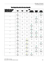
Страница 179: ...ple the first 2 tests are conducted Operating time Explanation 0 15 2 s LED test All 7 LEDs are activated 2 5 s Visual display of the position of the rotary coding switch 16 different positions are available for the rotary coding switch for setting the rated operational current Ie of the motor The table Visual display of the position of the rotary coding switch displays the exact position of the r...

Страница 180: ...ing If the error persists even though the connections are correct the 3RW5 soft starter must be replaced If a 3RW5 HMI is connected to the 3RW5 soft starter the 3RW5 indicates Motor overload tripping when it passes the function test If the 3RW5 soft starter does not pass the function test the 3RW5 HMI indicates a device error LED test LED Display of test result pass fail RN Lights up green Off ER ...

Страница 181: ...ckers green Off Off Off Lights up green Lights up green 4 Flickers green Off Off Lights up green Off Off 5 Flickers green Off Off Lights up green Off Lights up green 6 Flickers green Off Off Lights up green Lights up green Off 7 Flickers green Off Off Lights up green Lights up green Lights up green 8 Flickers green Off Lights up yellow Off Off Off 9 Flickers green Off Lights up yellow Off Off Ligh...

Страница 182: ... Off Off Off Current detection test LED Display of test result pass fail STATE OVERLOAD Flickers red Off In case of error System LEDs RN ER MT flashing Device error replace device Motor overload protection test Display of test result pass fail STATE OVERLOAD LED Flashes red Off In case of error System LEDs RN ER MT flashing Device error replace device ER LED Flashes red In case of error System LED...

Страница 183: ... a fieldbus via a 3RW5 communication module only via a 3RW5 PROFINET or PROFIBUS communication module With SIRIUS Soft Starter ES TIA Portal Premium Configuration software of the control system e g STEP 7 with corresponding HSP Logbook application The logbook application contains all messages relating to functions and parameters This logbook is only available in the 3RW50 soft starter The logbook ...

Страница 184: ...Messages and diagnosis 8 11 Logbooks SIRIUS 3RW50 soft starter 184 Manual 09 2019 A5E35628455002A RS AA 001 ...

Страница 185: ...specialist personnel Repair of the devices is only permissible by qualified personnel Contact the authorized Siemens service partner for this If the 3RW5 soft starter detects a replacement part the menu item Parameters Soft Starter Spare part Article No appears in the 3RW5 HMI High Feature Note Loss of ATEX IECEx approval The repair of devices with approval according to IEC 61508 EN 13849 is only ...

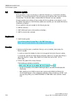
Страница 186: ...firmware update You will find the latest firmware files on the 3RW5 topic page https support industry siemens com cs ww en view 109747404 Procedure 1 Make sure that the motor is switched off and you do not start the motor during the firmware update A control command for starting the motor is not supported during the firmware update To ensure the quickest and most fault free firmware update it is r...

Страница 187: ... A5E35628455002A RS AA 001 187 Result You have performed a firmware update for the selected device The selected device automatically restarts Note Firmware update of the 3RW5 HMI High Feature Please note that the display switches off for about 30 seconds when the firmware is activated ...

Страница 188: ...MI High Feature during updating of the firmware Premature removal of the micro SD card from the 3RW5 HMI High Feature is not permissible and will terminate updating of the firmware Data could also be lost 1 Select the folder of the respective device 2 Select the firmware file of the device and confirm with the OK key You can see the firmware update is being performed from the progress bar on the d...

Страница 189: ...o the factory settings as described above Possible factory settings The following procedures are possible With the MODE and RESET TEST Page 192 keys Via the 3RW5 HMI High Feature Restoring the factory settings via High Feature 3RW5 HMI Page 190 Restoring the factory settings with the Master RESET button via 3RW5 HMI High Feature Page 191 Via the local interface on the 3RW5 HMI High Feature with SI...

Страница 190: ...t is recommended that you disconnect the main voltage at the 3RW5 soft starter 3RW5 HMI High Feature Menu Parameters Factory settings Access protection to 3RW5 HMI High Feature is not active or has been removed The 3RW5 HMI High Feature LOCAL has master control Procedure 1 Select the desired menu item Soft starter Communication module HMI High Feature All devices 2 Confirm the menu item by pressin...

Страница 191: ...e main voltage at the 3RW5 soft starter Free access to the Master RESET key of the 3RW5 HMI High Feature 3RW5 HMI High Feature is connected to the 3RW5 soft starter via the HMI connecting cable Procedure 1 Press the Master RESET key on the rear of the 3RW5 HMI High Feature The menu for restoring the factory setting appears on the display 2 Select the desired menu item Soft starter Communication mo...

Страница 192: ...ule must be isolated from the 3RW50 soft starter Procedure 1 Start the restoration of the factory settings by pressing the MODE key longer than 2 s until the STATE OVERLOAD LED flickers green Press and hold the MODE key 2 Simultaneously press the RESET TEST key down for at least 10 s After 2 s the STATE OVERLOAD LED begins to illuminate red After 10 s the STATE OVERLOAD LED goes out and switches b...

Страница 193: ...ustry Online Support https support industry siemens com cs ww en ps 16212 td 1 Enter the full article number of the desired device in the Product field and confirm with the Enter key 2 Click the Technical data link Overview tables technical data You will find overview tables with technical data in the Product information tab in our online ordering system https mall industry siemens com mall en WW ...

Страница 194: ...Technical specifications 10 1 Technical data in Siemens Industry Online Support SIRIUS 3RW50 soft starter 194 Manual 09 2019 A5E35628455002A RS AA 001 ...

Страница 195: ...n drawings 11 11 1 CAx data You can find the CAx data in the Siemens Industry Online Support https support industry siemens com cs ww en ps 16212 td 1 Enter the full article number of the desired device in the Product field and confirm with the Enter key 2 Click the CAx data link ...

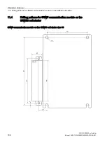
Страница 196: ... 3RW5 HMI Standard SIRIUS 3RW50 soft starter 196 Manual 09 2019 A5E35628455002A RS AA 001 11 2 Drilling pattern for 3RW5 HMI Standard The drilling pattern below supports you when installing a 3RW5 HMI Standard with push in lugs on a level surface ...

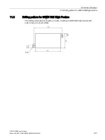
Страница 197: ...HMI High Feature SIRIUS 3RW50 soft starter Manual 09 2019 A5E35628455002A RS AA 001 197 11 3 Drilling pattern for 3RW5 HMI High Feature The drilling pattern below supports you when installing a 3RW5 HMI High Feature with push in lugs on a level surface ...

Страница 198: ...mmunication module on the 3RW50 soft starter SIRIUS 3RW50 soft starter 198 Manual 09 2019 A5E35628455002A RS AA 001 11 4 Drilling patterns for 3RW5 communication module on the 3RW50 soft starter 3RW5 communication module on the 3RW50 soft starter size S6 ...

Страница 199: ...ings 11 4 Drilling patterns for 3RW5 communication module on the 3RW50 soft starter SIRIUS 3RW50 soft starter Manual 09 2019 A5E35628455002A RS AA 001 199 3RW5 communication module on the 3RW50 soft starter size S12 ...

Страница 200: ...Dimension drawings 11 4 Drilling patterns for 3RW5 communication module on the 3RW50 soft starter SIRIUS 3RW50 soft starter 200 Manual 09 2019 A5E35628455002A RS AA 001 ...

Страница 201: ... diagrams 12 12 1 CAx data You can find the CAx data in the Siemens Industry Online Support https support industry siemens com cs ww en ps 16212 td 1 Enter the full article number of the desired device in the Product field and confirm with the Enter key 2 Click the CAx data link ...

Страница 202: ...Circuit diagrams 12 1 CAx data SIRIUS 3RW50 soft starter 202 Manual 09 2019 A5E35628455002A RS AA 001 ...

Страница 203: ... type of coordination 1 fuseless Feeder assembly type of coordination 1 fuseless The connections of the 3RW50 soft starter are wired into the motor feeder between the motor starter protector and the motor This achieves type of coordination 1 Q1 Motor starter protector e g 3RV2 or 3VA Q11 3RW50 soft starter M1 Motor PE Protective conductor ...

Страница 204: ...otor The 3RW50 soft starter could otherwise indicate a Missing load voltage fault in case of a start command and delayed connection of the contactor Feeder assembly type of coordination 1 with fuses If galvanic isolation is required install a main or line contactor between the 3RW50 soft starter and the fuses F1 gG full range fuse for cable and line protection e g 3NA3 Q21 Main or line contactor f...

Страница 205: ...n for all thyristors against short circuits by means of special semiconductor fuses e g SITOR fuses from Siemens A short circuit can occur for instance as a result of a defect in the motor windings or in the motor s power supply cable Q1 Motor starter protector F3 aR partial range fuse for protection of semiconductors e g SITOR 3NE3 4 or 3NC3 F3 gR full range fuse for protection of semiconductors ...

Страница 206: ...uirements ON RUN relay output was parameterized to ON Wiring of control circuit for control by pushbutton F1 Fuse S1 Pushbutton Start motor S2 Pushbutton Reset 4 s S4 Pushbutton Stop motor Q1 Motor starter protector Q11 3RW50 soft starter M1 Motor PE Protective conductor Alternatively the motor feeder can be assembled as a fuseless or fused version with type of coordination 1 or 2 ...

Страница 207: ...y after the reset This particularly applies if the motor protection has tripped Dangerous states of the system can result Reset the start command e g via the PLC or switch before performing a reset To do this for example link the group error output terminals 95 and 96 into the control Wiring of control circuit for control by switch F1 Fuse S1 Switch S2 Pushbutton Reset 4 s Q1 Motor starter protect...

Страница 208: ...he device is switched on and off in normal operation by means of the control supply voltage WARNING Automatic restart Can cause death or serious injury If a starting command is pending a restart will be triggered automatically after the reset This particularly applies if the motor protection has tripped Dangerous states of the system can result Reset the start command e g via the PLC or switch bef...

Страница 209: ...al 09 2019 A5E35628455002A RS AA 001 209 Wiring control circuit on switching with the control supply voltage F1 Fuse S1 Switch Reset 4 s OFF Q1 Motor starter protector Q11 3RW50 soft starter M1 Motor P1 Indicator light P2 Indicator light P3 Indicator light PE Protective conductor ...

Страница 210: ...ending a restart will be triggered automatically after the reset This particularly applies if the motor protection has tripped Dangerous states of the system can result Reset the start command e g via the PLC or switch before performing a reset To do this for example link the group error output terminals 95 and 96 into the control Wiring of control circuit for control by PLC F1 Fuse K1 Coupling re...

Страница 211: ...RNING Automatic restart Can cause death or serious injury If a starting command is pending a restart will be triggered automatically after the reset This particularly applies if the motor protection has tripped Dangerous states of the system can result Reset the start command e g via the PLC or switch before performing a reset To do this for example link the group error output terminals 95 and 96 ...

Страница 212: ...anual 09 2019 A5E35628455002A RS AA 001 Wiring of control circuit for controlling a line contactor F1 Fuse S1 Switch S2 Pushbutton Reset 4 s Q1 Motor starter protector Q11 3RW50 soft starter Q21 Line contactor M1 Motor P1 Indicator light P3 Indicator light PE Protective conductor ...

Страница 213: ... Control current connection SIRIUS 3RW50 soft starter Manual 09 2019 A5E35628455002A RS AA 001 213 A 2 6 Wiring for remote RESET Procedure Result You can reset a pending error message by operating the reset button for 4 s ...

Страница 214: ...s T11 T12 Note 3RW50 soft starter with thermistor motor protection in hazardous areas Note that the operation of a 3RW50 soft starter with thermistor motor protection in hazardous areas is only possible with a thermistor e g PTC Type A You will find additional information on the operation of motors in hazardous areas in Chapters ATEX IECEx certified motor overload protection Page 133 and Thermisto...

Страница 215: ...oft starter with analog output Evaluation unit for displaying the analog output signal Parameterized analog output Parameterizing analog output AQ via the High Feature 3RW5 HMI Page 111 Procedure Connect the evaluation unit Voltage at the terminals AQ U AQ Current at terminals AQ I AQ Result The actual average phase current of the motor is displayed in at the evaluation unit via the analog output ...

Страница 216: ... for ensuring certified motor overload protection according to ATEX IECEx Use an additional line contactor in the main circuit Connect the line contactor at outputs 95 96 and 98 output 3 For a motor feeder configuration with a circuit breaker use an additional undervoltage trip unit Connect the undervoltage trip unit at outputs 95 96 and 98 output 3 For more information see Chapter Connections Pag...

Страница 217: ...9 2019 A5E35628455002A RS AA 001 217 Wiring of control circuit for controlling a line contactor F1 Fuse S1 Switch S2 Pushbutton Reset 4 s Q1 Motor starter protector Q11 3RW50 soft starter Q21 Line contactor M1 Motor P1 Indicator light P3 Indicator light PE Protective conductor ...

Страница 218: ...f a starting command is pending a restart will be triggered automatically after the reset This particularly applies if the motor protection has tripped Dangerous states of the system can result Reset the start command e g via the PLC or switch before performing a reset To do this for example link the group error output terminals 95 and 96 into the control Wiring F1 Fuse S1 Switch S2 Pushbutton Res...

Страница 219: ...onsidered in the safety application and also does not have to be included in the calculation for proof according to the standards If achievement of SILCL 1 according to IEC 62061 2005 or PL c according to EN ISO 13849 1 2015 is required the series connection of an additional contactor with the 3RW50 soft starter in conjunction with a suitable safety relay e g 3SK1111 is required as well as monitor...

Страница 220: ...gerous states of the system can result Reset the start command e g via the PLC or switch before performing a reset To do this for example link the group error output terminals 95 and 96 into the control Tripping of the EMERGENCY STOP circuit If the soft stop function is set stopping time setting element set to 0 s and the emergency stop circuit is tripped a Missing load voltage phase failure missi...

Страница 221: ...cuits A 3 Special applications SIRIUS 3RW50 soft starter Manual 09 2019 A5E35628455002A RS AA 001 221 Wiring Wiring of the 3SK1 safety relay Q21 Contactor S3 Start button S4 Emergency stop K1 3SK1111 safety relay ...

Страница 222: ... soft starter 222 Manual 09 2019 A5E35628455002A RS AA 001 Wiring of the 3RW50 soft starter F1 Fuse S1 Switch Start stop S2 Pushbutton Reset 4 s Q1 Motor starter protector Q11 3RW50 soft starter Q21 Contactor P1 Indicator light P2 Indicator light M1 Motor ...

Страница 223: ...ively nor negatively considered in the safety application and also does not have to be included in the calculation for proof according to the standards Safe shutdown up to SILCL 3 according to IEC 62061 2005 and PL e according to EN ISO 13849 1 2015 requires the use of 2 redundant contactors and monitoring of the auxiliary contacts of both contactors Two channel monitoring of the EMERGENCY STOP is...

Страница 224: ...gerous states of the system can result Reset the start command e g via the PLC or switch before performing a reset To do this for example link the group error output terminals 95 and 96 into the control Tripping of the EMERGENCY STOP circuit If the soft stop function is set stopping time setting element set to 0 s and the emergency stop circuit is tripped a Missing load voltage phase failure missi...

Страница 225: ... 3 Special applications SIRIUS 3RW50 soft starter Manual 09 2019 A5E35628455002A RS AA 001 225 Wiring Wiring of the 3SK1 safety relay Q21 Contactor Q22 Contactor S3 Start button S4 Emergency stop K1 3SK1111 safety relay ...

Страница 226: ...tarter 226 Manual 09 2019 A5E35628455002A RS AA 001 Wiring of the 3RW50 soft starter F1 Fuse S1 Switch Start stop S2 Pushbutton Reset 4 s Q1 Motor starter protector Q11 3RW50 soft starter Q21 Contactor Q22 Contactor P1 Indicator light P2 Indicator light M1 Motor ...

Страница 227: ... be triggered automatically after the reset This particularly applies if the motor protection has tripped Dangerous states of the system can result Reset the start command e g via the PLC or switch before performing a reset To do this for example link the group error output terminals 95 and 96 into the control Note Loss of the certified motor overload protection according to ATEX IECEx Note that t...

Страница 228: ...8455002A RS AA 001 Wiring F1 Fuse S1 Switch S2 Pushbutton Reset 4 s Sn Soft start selector button Sn1 Start stop direct on line starting Q1 Motor starter protector Q11 3RW50 soft starter Q21 Direct on line starting contactor P1 Indicator light fault P2 Indicator light P3 Indicator light M1 Motor ...

Страница 229: ... not unrestricted LGPL Licensed Module whereas the LGPL Licensed Module and the components that the LGPL Licensed Module is combined with or linked to is the Combined Product the following additional rights apply if the relevant LGPL license criteria are met i you are entitled to modify the Combined Product for your own use including but not limited to the right to modify the Combined Product to r...

Страница 230: ... doubt SIEMENS does not make any warranty commitment on behalf of or binding upon any third party licensor Open Source Software and or other third party software contained in this Product If you like to receive a copy of the source code please contact SIEMENS at the following address Siemens AG LC TE SL Werner von Siemens Str 60 91052 Erlangen Germany Subject Open Source Request please specify Pro...

Страница 231: ...sion THIS SOFTWARE IS PROVIDED BY THE COPYRIGHT HOLDERS AND CONTRIBUTORS AS IS AND ANY EXPRESS OR IMPLIED WARRANTIES INCLUDING BUT NOT LIMITED TO THE IMPLIED WARRANTIES OF MERCHANTABILITY AND FITNESS FOR A PARTICULAR PURPOSE ARE DISCLAIMED IN NO EVENT SHALL THE COPYRIGHT OWNER OR CONTRIBUTORS BE LIABLE FOR ANY DIRECT INDIRECT INCIDENTAL SPECIAL EXEMPLARY OR CONSEQUENTIAL DAMAGES INCLUDING BUT NOT ...

Страница 232: ...Third party software B 1 Information about third party software SIRIUS 3RW50 soft starter 232 Manual 09 2019 A5E35628455002A RS AA 001 ...

Страница 233: ...tem GSDML Generic station description file This file is required in order to configure a device as a PN device in the HW Config of a Siemens or external system HSP Hardware support package The hardware support packages allow you to configure modules that are not listed in the hardware catalog of your TIA Portal installation Manual RESET Manual RESET means that the following options are available f...

Страница 234: ...ng data sets Remote RESET Remote RESET means that faults are acknowledged by switching the control supply voltage off and on again The control supply voltage on the 3RW50 soft starter must be switched off for at least 4 s STS Simulation Tool for Soft Starters The soft starter can be configured with the STS Simulation Tool for Soft Starters software The STS suggests suitable soft starters for the a...

Страница 235: ...arameter assignment 111 App Siemens Industry Online Support 36 Applications 22 Auto RESET 98 173 C Catalog 33 CAx data 35 195 201 Circuit diagram example Actuation of a line contactor 211 Connecting the evaluation unit to the analog output 215 Connecting the temperature sensor 214 Contactor for emergency starting 227 Control by PLC 210 Control by pushbutton 206 Control by switch 207 Control of a m...

Страница 236: ...3RW5 HMI High Feature 172 Feeder assembly type of coordination 1 fuseless 203 Feeder assembly type of coordination 1 with fuses 204 Feeder assembly type of coordination 2 205 Firmware update 186 Five safety rules for electricians 42 Function test 179 Functions 12 Additional parameters 136 Control via digital input 139 Current limiting function 123 Soft starting 119 125 Thermistor motor protection ...

Страница 237: ...ditional parameters 136 Control via digital input 139 Overview 93 Parameterizing mode 101 Process image Monitoring 149 Product data sheet 195 201 Push in lugs 27 R Reactive power compensation 41 References 32 Remote RESET 98 173 Removing On a level surface 68 Repairs 185 Replacing Control terminals 83 Terminals 76 RESET MODE 96 S Safety rules 42 Screw terminals Connecting 79 Control current 80 Sel...

Страница 238: ... SIRIUS 3RW50 soft starter 238 Manual 09 2019 A5E35628455002A RS AA 001 W Warnings and remedial measures 167 Wiring for ATEX IECEx applications with additional line contactor 216 Wiring for remote RESET 213 ...

Отзывы: