Addressing and installation
4.1 Address Assignments in the CPU
Fail-safe signal modules
32
Installation and Operating Manual, 01/2010, A5E00085586-10
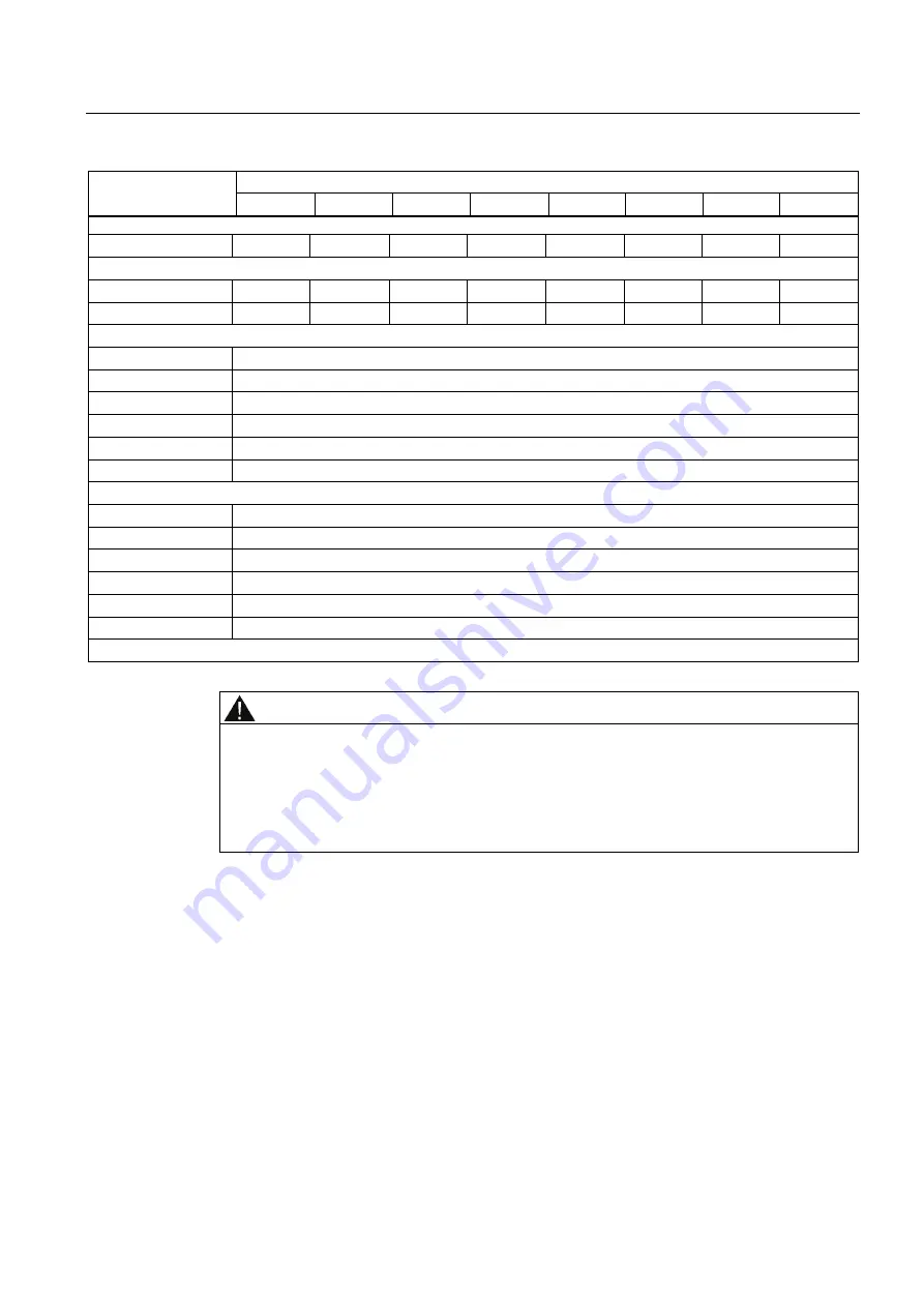
Assigned bits in the CPU for each module:
Bytes in the CPU
7
6
5
4
3
2
1
0
SM 326; DO 8 x DC 24V/2A PM:
x + 0
Channel 7 Channel 6 Channel 5 Channel 4 Channel 3 Channel 2 Channel 1 Channel 0
SM 326; DO 10 x DC 24V/2A and SM 326; F-DO 10 x DC 24V/2A PP:
x + 0
Channel 7 Channel 6 Channel 5 Channel 4 Channel 3 Channel 2 Channel 1 Channel 0
x + 1
—
—
—
—
—
—
Channel 9 Channel 8
SM 336; AI 6 x 13Bit:
x + 0, x + 1
Channel 0
x + 2, x + 3
Channel 1
x + 4, x + 5
Channel 2
x + 6, x + 7
Channel 3
x + 8, x + 9
Channel 4
x + 10, x + 11
Channel 5
SM 336; F-AI 6 x 0/4 ... 20 mA HART:
x + 0, x + 1
Channel 0
x + 2, x + 3
Channel 1
x + 4, x + 5
Channel 2
x + 6, x + 7
Channel 3
x + 8, x + 9
Channel 4
x + 10, x + 11
Channel 5
x = module start address
WARNING
You may only access the addresses occupied by the user data both in the standard user
program and the safety program. Other address areas occupied by the F-SMs are
assigned, for example, for safety-oriented communication between the F-SMs and the F-
CPU in accordance with PROFIsafe.
With 1oo2 sensor evaluation of modules in safety mode, you may access only the lower
order channel of the channels combined by the 1oo2 sensor evaluation.
Содержание Simatic S7-300
Страница 326: ...Response times D 1 Response Times Fail safe signal modules 326 Installation and Operating Manual 01 2010 A5E00085586 10 ...
Страница 344: ...Glossary Fail safe signal modules 344 Installation and Operating Manual 01 2010 A5E00085586 10 ...
Страница 356: ...Product Information 4 A5E03004206 01 ...