


Installing system components
3.6 Connecting the connection box
TP1000F Mobile RO
Operating Instructions, 08/2017, A5E39831415-AA
59
Requirement
●
The connection box is mounted.
●
Connection box compact:
–
1 preassembled Ethernet cable including Ethernet connector.
Recommendation: Use an angled connector, for example, an RJ45 connector with
article number 6GK1901-1BB20-2Ax0.
x stands for the variant key of the article number.
●
Connection boxes standard and advanced:
–
The connection box is open.
–
1 Ethernet cable (not preassembled)
–
1 screwdriver, PZ 2
–
1 stripping tool
See the online catalog at "Industry Mall (
https://mall.industry.siemens.com
)".
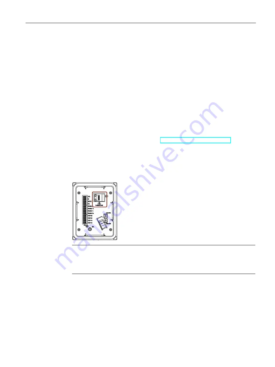
Procedure
Connection box compact
1.
Plug the RJ45 connector on the Ethernet cable into the interface indicated.
Note
LEDs on the RJ45 socket not active
The two LEDs at the RJ45 socket of the connection box compact are not supported by
the hardware and do not light up during operation.