background image


Geared motors 


5.4 Technical specifications 

ATD4xxW Door Controller for Industrial Applications 
System Manual, 01/2017, A5E38080677-AB 

209


5.4.5


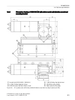
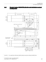
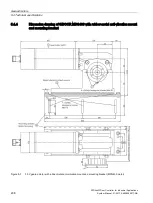
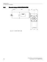
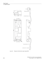
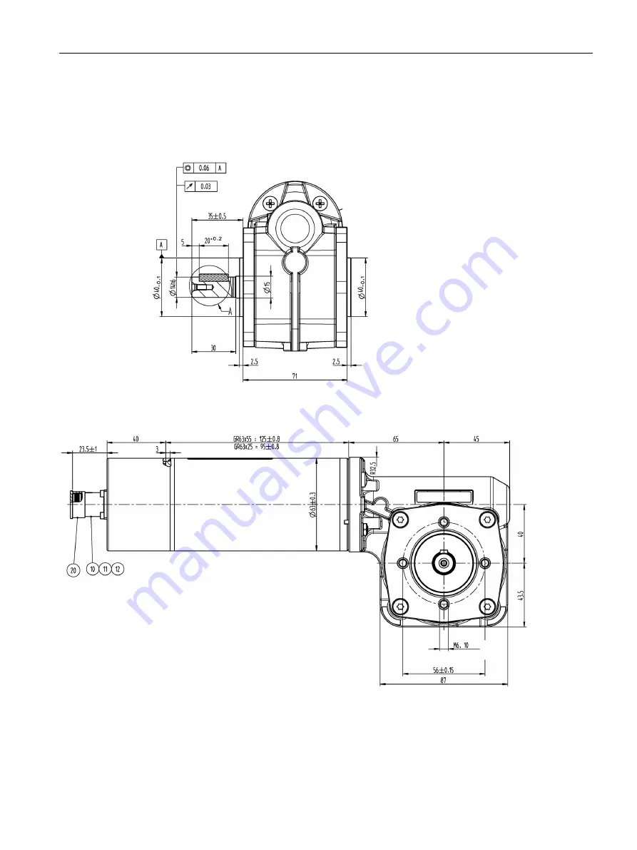
Dimension drawing MDG400NMS 

Front view 


Side view 


Содержание SIDOOR ATD401W

Страница 1: ......

Страница 2: ...__________________ ___________________ Automatic door controllers SIDOOR ATD4xxW Door Controller for Industrial Applications System Manual 01 2017 A5E38080677 AB Preface Sign posts 1 System overview 2 SIDOOR functions 3 Controllers 4 Geared motors 5 Power supply 6 SIDOOR Service Tool 7 Configuration and programming in STEP 7 8 Connecting and commissioning 9 Diagnostic and maintenance 10 Appendices...

Страница 3: ... only by personnel qualified for the specific task in accordance with the relevant documentation in particular its warning notices and safety instructions Qualified personnel are those who based on their training and experience are capable of identifying risks and avoiding potential hazards when working with these products systems Proper use of Siemens products Note the following WARNING Siemens p...

Страница 4: ...ATD4xxW control gear at Industry Online Support http support automation siemens com WW view en 50247080 133100 Figures The illustrations in this system manual show the SIDOOR User Software Version 1 2 and the SIDOOR command device The illustrations for other versions may differ slightly Information on the Internet You can find more information about SIDOOR door drives and their application on the ...

Страница 5: ...ed to the enterprise network or the Internet if and to the extent necessary and with appropriate security measures e g use of firewalls and network segmentation in place Additionally Siemens guidance on appropriate security measures should be taken into account You can find more information on industrial security at http www siemens com industrialsecurity Siemens products and solutions undergo con...

Страница 6: ...digital inputs 43 3 1 6 DOOR OPEN command given via digital inputs 44 3 1 7 Stopping 45 3 1 8 Partial opening 45 3 1 9 Obstruction detection CLOSE 46 3 1 10 Obstruction detection OPEN 46 3 1 11 Force and energy profiles NDG mode 47 3 1 12 Slow driving curve profile 48 3 1 13 DCOPS door closed opened position sensor 49 3 2 System functions 51 3 2 1 Restart after power failure 51 3 2 2 Initial run r...

Страница 7: ...locks 81 3 3 9 6 Discrepancy analysis blocks 81 3 3 9 7 Basic blocks 81 3 3 9 8 Frequency analysis blocks 82 3 3 9 9 On delay block 82 3 3 9 10 Counter block 83 3 3 10 Basic parameter editor as of V1 10 83 3 4 Safety functions 85 3 4 1 Optional safety equipment 85 3 4 1 1 Light barrier 85 3 4 1 2 Type 2 ESPE 87 3 4 1 3 Pressure sensitive edge SR 89 3 4 2 Security policy 90 3 4 2 1 Safe force outpu...

Страница 8: ...5 4 PROFINET 134 4 5 4 1 PROFINET module 134 4 5 4 2 Wiring and connecting a PROFINET connector 141 4 5 4 3 Wiring and connecting relay outputs 142 4 5 4 4 PROFINET communication 144 4 5 5 Local master operation 148 4 5 6 Master monitoring 148 4 6 Sequential control 149 4 7 Sensors and external sensor interface module 152 4 7 1 Overview 152 4 7 2 Sensor function test 155 4 7 3 Reaction times 156 4...

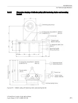
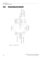
Страница 9: ...0 NMS with rubber metal anti vibration mount and mounting bracket 210 5 4 7 Dimension drawing of SIDOOR M5 211 5 4 8 Dimension drawing of SIDOOR MDG700 NMS 212 5 4 9 Dimension drawing of MDG motor cable 213 5 4 10 Dimension drawing of motor cable MDG2 214 5 4 11 Dimension drawing of deflector pulley with tensioning device and mounting bracket 215 5 4 12 Dimension drawing of door clutch holder 216 ...

Страница 10: ... GSD file 255 8 3 Programming SIDOOR instructions 256 8 3 1 SIDOOR_CDat data type 257 8 3 2 SIDOOR_SDat data type 258 9 Connecting and commissioning 259 9 1 Overview of safety and commissioning 259 9 2 Preparing the control unit 263 9 3 Connecting a geared motor to the control unit 264 9 4 Connecting the power supply to the network and executing a learn run 266 9 5 Connecting digital inputs 267 9 ...

Страница 11: ...ology control word 2 289 A 1 2 5 ZSW1 status word StatW 290 A 1 2 6 TZW0 Technology status word 0 292 A 1 2 7 TZW1 Technology status word 1 292 A 1 2 8 TZW2 Technology status word 2 295 A 1 2 9 TZW3 TZW4 TZW5 Technology status words 3 4 5 297 A 2 Profiles and adjustment ranges 299 A 2 1 Profile name 299 A 2 2 SIDOOR M3 L R 299 A 2 3 SIDOOR MDG180 L R 301 A 2 4 SIDOOR M4 L R 301 A 2 5 SIDOOR MDG400...

Страница 12: ...of the SIDOOR devices The devices that you can use together The article numbers for ordering these devices Information on installation Important safety information Where you can get more information about the devices Documentation download This documentation is available for download free of charge on the Internet http www siemens com automation service support Changes and additions to the manuals...

Страница 13: ...s Applications Tools support you with various tools and examples for solving your automation tasks Solutions are shown in interplay with multiple components in the system separated from the focus on individual products You can find Applications Tools on the Internet https support industry siemens com cs ww en ps 18286 ae ...

Страница 14: ...the controller of an access system Door control systems are characterized by the fact that there are always two defined states namely for the open and closed positions of the door The door is always controlled between these two positions in accordance with the guidelines of the respective application SIDOOR for industrial applications Door control systems for industrial applications are designed m...

Страница 15: ...he drive direction of the geared motor and stores these data in a non volatile memory Assisted Drive and Impulse Stop support the movement of the heaviest doors without buttons or sensors Impulse Drive allows doors to be opened at closed with a brief light touch The door moves completely autonomously The screwless enclosure concept with plug in terminal connectors allows the device to be opened an...

Страница 16: ...onal unit e g SIDOOR Service Tool SIDOOR Software Kit Geared motor Accessories Power supply Sliding door Figure 2 1 System configuration System configuration with a communication link A system configuration with a communication link to the higher level control such as SIMATIC S7 via PROFIBUS or PROFINET is furthermore possible System configuration with safety functionality SIDOOR also provides a s...

Страница 17: ... The controller is interfaced to a USS bus by means of a permanently integrated USS module You can find additional information about the USS protocol online at Industry Online Support http support automation siemens com WW view de 24178253 0 en SIDOOR ATD420W The PROFIBUS DP interface is realized with a permanently integrated PROFIBUS module This module comes with its own firmware SIDOOR ATD430W T...

Страница 18: ...red via a user interface The controllers are designed for different areas of application Controllers for industrial applications The following table provides an overview of the control units for doors in industrial applications Controller Article No Description SIDOOR ATD401W 6FB1141 1AT11 3WE2 Relay module SIDOOR ATD410W 6FB1141 4AT10 3WE2 USS bus interface to the higher level controller USS modu...

Страница 19: ... motor pinion right max 180 kg door weight Cable length 1 5 m SIDOOR MDG180 L 6FB1103 0AT14 4MB0 Geared motor pinion left max 180 kg door weight Without cable SIDOOR MDG180 R 6FB1103 0AT13 4MB0 Geared motor pinion right max 180 kg door weight Without cable SIDOOR M4 L 6FB1103 0AT10 3MC0 Geared motor pinion left max 400 kg door weight Cable length 1 5 m SIDOOR M4 R 6FB1103 0AT11 3MC0 Geared motor p...

Страница 20: ...r weight Without cable SIDOOR MDG700 NMS L 6FB1103 0AT14 3MG1 Geared motor without pinion max 700 kg door weight Without cable Cable can be ordered See section Accessories Page 21 2 3 3 Power supply SIDOOR power supplies connect the controllers to the respective application specific power supply Device selection Power supply Article No Description SITOP PSU8200 6EP3446 8SB10 0AY0 Power supply for ...

Страница 21: ...s mounted 6FB1104 0AT02 0AS0 Mounting bracket with tensioning device for deflector pulley For mounting the SIDOOR deflector unit and for tension ing the SIDOOR toothed belt SIDOOR deflector pulley 6FB1104 0AT04 0AS2 Deflector pulley for deflecting the SIDOOR toothed belt 1 unit SIDOOR deflector pulley 6FB1104 0AT04 0AS1 Deflector pulley for deflecting the SIDOOR toothed belt 30 units SIDOOR deflec...

Страница 22: ...Cable for connecting SIDOOR MDG180 R L MDG400 R L MDG400 NMS geared motors to SIDOOR ATD4xxW controllers Cable length 1 5 m SIDOOR CABLE MDG 5m 6FB1104 0AT05 0CB0 Cable for connecting SIDOOR MDG180 R L MDG400 R L MDG400 NMS geared motors to SIDOOR ATD4xxW controllers Cable length 5 m SIDOOR CABLE MDG 7m 6FB1104 0AT07 0CB0 Cable for connecting SIDOOR MDG180 R L MDG400 R L MDG400 NMS geared motors t...

Страница 23: ...ed motors and SIDOOR ATD4xxW control units Cable length 20 m PROFIBUS FC bus connector RS 485 6GK1500 0FC10 Bus connector with axial cable outlet 180 20m for connect ing SIDOOR ATD410W and SIDOOR ATD420W controllers to the USS PROFIBUS bus cable PROFIBUS FC Standard Cable GP 6XV1830 0EH10 PROFIBUS cable for connecting SIDOOR ATD410W and SIDOOR ATD420W controllers to the higher level SIMATIC contro...

Страница 24: ...ct to a deenergized controller via the interfaces provided and are available for use as soon as the power supply is connected Additional units The Service Tool SIDOOR is available as an accessory for door controllers in industrial applications Additional unit Article No Description SIDOOR Service Tool 6FB1105 0AT01 6ST0 The SIDOOR Service Tool may be used to input door com mands to change drive pa...

Страница 25: ...e Siemens HCS12 Firmware Loader Sidoor USB to UART Bridge driver License provisions SIDOOR Software Kit Operating Instructions 1 x USB adapter 1 x USB connecting cable 1x D SUB connecting cable 9 pin plug socket 1x D SUB connecting cable 9 pin socket socket The contents of the SIDOOR Software Kit installation CD are also available as an Installation Package http support automation siemens com WW v...

Страница 26: ...ctions that serve to extend the system with optional safety equipment and for using the inputs according to performance level d PL d Functions Table 3 1 Available SIDOOR functions Functions SIDOOR ATD401W ATD410W ATD4 20W ATD430W Basic functions Learn run Page 29 Force limit for learn run Page 37 as of V1 05 as of V1 05 Output transmission Page 38 as of V1 05 as of V1 05 Drive orders Page 39 CLOSE...

Страница 27: ...4 Friction compensation Page 55 Oscillation protection Page 56 Automatic energy limiting Page 57 External closing force Page 60 Extended functions ImpulseDrive Page 62 Automatic ImpulseDrive Page 64 ImpulseStop Page 65 Automatic ImpulseStop Page 66 AssistedDrive Page 67 Automatic AssistedDrive Page 69 Positioning mode Page 70 Obstruction detection Page 72 Free function blocks Page 76 Basic paramet...

Страница 28: ...ltaneously 4 Evaluated by PLC Drive function parameter assignment The relevant parameters for the drive functions in ATD401W control units can be changed to a limited extent The parameters are set via the integrated terminal module the optional SIDOOR Service Tool accessory or the software SIDOOR The drive functions listed above can be assigned parameters calibrated and configured on SIDOOR ATD410...

Страница 29: ...rn run Door width Effective door weight and counterweight Door friction Direction of rotation of the motor and pulse encoder As of V1 10 As an alternative to the learn run the basic parameters determined during the learn run can be configured using the basic parameters editor This allows initial commissioning of the SIDOOR door controller without a learn run see section Basic parameters editor Pag...

Страница 30: ...be moved is calculated from the sum of the mass equivalent of motor s rotor inertia the moving door mass and the moving mass of the door mechanism mrms mdoor mrot mmech mrms Mass to be moved mdoor Door mass mrot Mass equivalent of the rotor inertia of the motor mmech Moved mass of the door mechanism No general information can be provided here for the mass of the door mdoor and the moving mass of t...

Страница 31: ...Mass equivalent mrot 88 mm rev 86 kg 90 mm rev 82 kg 95 mm rev 74 kg 100 mm rev 67 kg 105 mm rev 60 kg 110 mm rev 55 kg 115 mm rev 50 kg 120 mm rev 46 kg 125 mm rev 43 kg 130 mm rev 39 kg 140 mm rev 34 kg 150 mm rev 30 kg 160 mm rev 26 kg 170 mm rev 23 kg 180 mm rev 21 kg 190 mm rev 18 kg 200 mm rev 17 kg 210 mm rev 15 kg 220 mm rev 14 kg 230 mm rev 13 kg 240 mm rev 12 kg 250 mm rev 11 kg 260 mm r...

Страница 32: ...ssion ratio Mass equivalent mrot 88 mm rev 367 kg 90 mm rev 351 kg 95 mm rev 315 kg 100 mm rev 284 kg 105 mm rev 258 kg 110 mm rev 235 kg 115 mm rev 215 kg 120 mm rev 197 kg 125 mm rev 182 kg 130 mm rev 168 kg 135 mm rev 156 kg 140 mm rev 145 kg 144 mm rev 135 kg 150 mm rev 126 kg 155 mm rev 118 kg 160 mm rev 111 kg 165 mm rev 104 kg 170 mm rev 98 kg 175 mm rev 93 kg ...

Страница 33: ...rev 79 kg 195 mm rev 75 kg 200 mm rev 71 kg 205 mm rev 68 kg 210 mm rev 64 kg 220 mm rev 59 kg 230 mm rev 51 kg 240 mm rev 49 kg 250 mm rev 45 kg 260 mm rev 42 kg 270 mm rev 39 kg 280 mm rev 36 kg 290 mm rev 34 g 300 mm rev 32 kg 310 mm rev 30 kg 320 mm rev 28 kg 330 mm rev 26 kg 340 mm rev 25 kg 350 mm rev 23 kg 360 mm rev 22 kg 370 mm rev 21 kg 380 mm rev 20 kg 388 mm rev 19 kg ...

Страница 34: ...SIDOOR functions 3 1 Basic functions ATD4xxW Door Controller for Industrial Applications 34 System Manual 01 2017 A5E38080677 AB Figure 3 2 MDG700NMS ...

Страница 35: ...h the determined door parameters The travel curve parameters and force and energy limiting parameters are retained Application examples modifying the properties of the door system door width or friction Learning new motors The learned motor type is stored in the controller and compared with the connected motor when the controller is switched on The controller s operating status display shows the s...

Страница 36: ...g the OPEN or CLOSE service buttons S402 or S403 Door command change except deenergized via the terminal the service interface or the fieldbus system Interruption of the ESPE or the pressure sensitive edge Querying determined values The values basic parameters determined from the learn run can be queried via the terminal module The SIDOOR ATD410W ATD420W ATD430W control units also allow you to que...

Страница 37: ...limit is set to the maximum value by default Note The force only needs to adjusted for easily moved door systems and door systems with soft end stops A smooth running door system has a mass to be moved 100 kg and maximum frictional forces of 20N Connection and parameter assignment The force limit can be configured via the terminal module Main menu General setup Special parameters Force limit for l...

Страница 38: ...on mm rev 300 Output transmis sion mm rev 384 100 kg 150 kg X X X X 200 kg 350 kg X X X n r 300 kg 500 kg X X n r n r 400 kg 700 kg X n r n r n r n r not recommended Note For the M4 MDG400 and M5 motors set default value to 176 mm rev Note The output transmission should be checked before each learn run and adjusted if necessary Note The determined door width has to be checked after each learn run ...

Страница 39: ...d Deenergize not a door command Stop Open Close Automatic AssistedDrive Page 69 Automatic ImpulseDrive Page 64 Positioning Page 70 Learn run Page 29 Slow Page 48 x x x x x ImpulseStop Page 65 Automatic ImpulseStop Page 66 NDG Page 47 x x x x x Special Corresponds to Deener gize source voltage brake inac tive Learn run with a new motor Page 29 Partial Page 45 x x x x DCOPS Page 49 x x x LB sensor P...

Страница 40: ...ring In SIDOOR systems coasting down is equivalent to the Deenergize no current door command For safety reasons however direct coasting down must not take place due to the limits implemented in a door system safety reasons This is why the following definitions apply to the SIDOOR door drive Table 3 5 SIDOOR door drive shutdown deceleration functions limited system Function Description Not a door c...

Страница 41: ... with new motor drive orders using the terminal Main menu General setup or Quick setup Software Kit PC Drive orders can be simulated via the Drive orders window The following applies to the ATD4xxW Open Open drive order Close Close drive order Nudge NDG close drive order Stop Stop drive order Process data USS PROFIBUS PROFINET FBLOCK system digital INPUT1 2 3 4 and X5 Process data Drive orders can...

Страница 42: ...hed Only in the case of edge controlled digital input signals of the FBLOCK system latched drive orders Mutual prioritization of door commands When a command is issued via the process image there can be no mutual prioritization of door commands because the corresponding DCMD signal is based on an enumerative structure and therefore only ever one door command can be active Prioritization is applied...

Страница 43: ...R and OPEN DOOR are present simultaneously the door always moves in the OPEN direction SIDOOR ATD410W ATD420W ATD430W See also section Free function blocks FBLOCK Page 76 Note As an alternative the signal can also be evaluated via the PLC process image Connection SIDOOR ATD401W The CLOSE DOOR function is connected to Input 3 X6 See also section Digital input signals Page 108 For the door commands ...

Страница 44: ...ver all other control commands Note If the commands CLOSE DOOR and OPEN DOOR are present simultaneously the door always moves in the OPEN direction SIDOOR ATD410W ATD420W ATD430W See also section Free function blocks FBLOCK Page 76 Note As an alternative the signal can also be evaluated via the PLC process image Connection SIDOOR ATD401W The OPEN DOOR function is connected to Input 3 X6 See also s...

Страница 45: ... and second open positions when partial opening mode is activated this is detected as an invalid area In this area the controller reduces the drive s speed automatically The normal curve profile becomes active again as soon as the drive has moved out of the invalid area or has exited partial opening mode The scenario described is not to be evaluated as a fault or an invalid situation The continuou...

Страница 46: ...2 cm past the stored position of the obstruction and then continues the rest of the way at normal closing speed For more see also section Obstruction detection SIDOOR ATD4xxW Page 71 As of V1 09 If the door has been in the CLOSE position for at least 3 seconds and it is then subjected to extreme force with the pending command CLOSE DOOR the travel in the CLOSE direction will detect no obstruction ...

Страница 47: ...4 MaxSpdOp Drive order for profile switching To switch to NDG mode the DCMD expansion bit NDG must be set see Table A 17 DCMD expansion bits Page 288 In combination with an applicable DCMD drive order see Table A 16 DCMD signal Page 287 the drive travels with the NDG force and energy profile Switching profiles The drive switches over to the NDG force and energy profile when the corresponding drive...

Страница 48: ...dCls p3664 MaxSpdOp p3672 NdgSpd Drive order for profile switching To switch to the slow profile the DCMD expansion bit slow see Table A 17 DCMD expansion bits Page 288 must be set In combination with an applicable DCMD drive order see Table A 16 DCMD signal Page 287 the drive switches to the slow profile Switching profiles The drive switches over to the slow profile when the corresponding drive o...

Страница 49: ...er switches directly to normal mode with a corresponding Open or Close drive order when an obstruction end stop is detected To prevent the erroneous detection of a blocking obstruction as an end stop the DCOPS signal must not be activated until 1 to 2 cm before the respective end stop Example sequence when using DCOPS 1 Power ON 2 Controller is in the initial mode No fault present The system is in...

Страница 50: ...S signal can be sent as shown in Figure 4 5 Sensor signals Page 152 via the process image see Table A 17 DCMD expansion bits Page 288 and or via the local sensor input Input 1 via p4600 see Table 4 33 Other parameters Page 176 Note The status of the sequential control must be considered when using the DCOPS signal process image The process data is only valid in the S4 Z_ operation state see Figure...

Страница 51: ...d positions of the door travel To do this the door travels at reduced speed initial speed until the controller has detected the OPEN and CLOSED end positions The door then resumes traveling at normal speed The door travels at normal speed immediately if the DCPS is installed see section DCOPS door closed opened position sensor Page 49 In this case the door must be in the CLOSED position for the re...

Страница 52: ...ed in initial mode is adjustable via the parameter p1208 With power On the sequential control system is in the state S1 Z_closing lockout applies only to ATD410W ATD420W and ATD430W see Sequential control Page 149 Using an end position sensor You can skip initial mode by connecting a DCOPS end position sensor Door Closed Opened Position Sensor Depending on the application 1 end position sensor can...

Страница 53: ...ctively decelerates the motor to 50 mm s and then switches the drive back to deenergize As of V1 10 The maximum vandalism prevention speed for the motors M5 and MDG700NMS is 200mm s SIDOOR ATD410W ATD420W ATD430W If the maximum configurable speed p1200 is exceeded the controller actively decelerates the motor to 50 mm s and then switches the drive back to deenergize Parameter assignment SIDOOR ATD...

Страница 54: ...Controller Distance Initial operation SIDOOR ATD4xxW Max door width 50 cm p1201 Normal operation SIDOOR ATD4xxW Learnt door width 50 cm p1201 Parameter assignment Belt break detection is suppressed if parameter p1201 is set to 0 In this case there is no fault or fault reaction on the part of the controller The status code t signals a torn belt The controller changes to the status S6 Z_Störung see ...

Страница 55: ...stant The measurement data are recorded every 2 cm the first measured value is recorded 2 cm after the trigger level position transient distance The measurement data are recorded in the closing direction throughout the entire closing movement within the learn run and after reaching the speed trigger level learn run speed As from this moment the door movement is almost constant The measurement data...

Страница 56: ... for 30 s with the set continuous torque without any response to further oscillations After a protective period of 30 s the system responds once again to corresponding oscillations End position closed If the system is pressed out of the end position with the drive order close present the system detects that the closed position has been left and attempts to return to the end stop with the set stati...

Страница 57: ...eded for specific applications if an additional protective device e g ESPE type 2 or pressure sensitive edge is used SIDOOR ATD4xxW controllers include a system that automatically limits the kinetic energy in the opening and closing directions The values for the energy limit are determined via the parameter p1202 in the closing direction or p1203 in the opening direction and P1204 NDG mode After s...

Страница 58: ...issible door speed closing speed vmax as a function of the total door panel weight According to Machinery Directive EN953 the maximum kinetic energy of the door in the closing direction must not exceed 10 joules WKIN 1 2 m v 10 J Example from the following speed limit curve Moved mass m 180 kg vmax 0 33 m s Figure 3 3 Speed limit curve for WKIN 10J If the reversing device is switched off the maxim...

Страница 59: ...um speeds The following table shows the maximum speeds depending on moved weight and energy limit Table 3 10 Maximum speeds mm s as a function of moving mass and energy limit Door weight kg Energy J 4 10 25 50 75 100 50 400 632 1000 1414 1732 2000 100 283 447 707 1000 1225 1414 150 231 365 577 816 1000 1155 200 200 316 500 707 866 1000 250 179 283 447 632 775 894 300 163 258 408 577 707 816 350 15...

Страница 60: ...ical parts Ensure that if there is an additional external closing force the sum of the external closing force and the force set in the controller does not exceed the maximum force limit of 150 N according to EN 953 Check the final application specific limit values and adjust the limit values accordingly 3 2 10 Synchronization of the door position Description of the function The determined door pos...

Страница 61: ...can be configured with the parameters p4700 p4701 and p4702 The following process values are available Digital inputs D IN Digital outputs D OUT Button Door position in mm Door setpoint speed in mm s Door actual speed in mm s Motor current in mA Motor current limitation in mA Voltage of the motor output stage in V Remaining power capacity of the braking resistor in J The default values of paramete...

Страница 62: ... Table A 30 IMPDRVIncr signal Page 295 and Table A 31 IMPDRVVelo signal Page 295 is generated The ImpulseDrive detection properties can be individually parameterized to enable adaption to different door systems Parameter assignment The detection algorithm consists of a distance and a speed component The sensitivity levels of both components can be parameterized separately p1221 and p1222 A paramet...

Страница 63: ...control state graph Page 149 and the lead time p1220 has expired The sensitivity level can be specified in parameter p1221 The higher it is the higher the number of increments counted before the signal IMPDRVInc changes to high active Speed based ImpulseDrive analysis The analysis is based on the increments of the motor encoder or the actual speed derived from it The evaluation is only made in the...

Страница 64: ...Drive system generates a drive order with a normal drive profile Both ImpulseDrive detection output signals IMPDRVVelo and IMPDRVIncr are evaluated If an enable command is present the automatic system initiates opening or closing with a normal drive profile The automatic ImpulseDrive can only be used with an active enable The enabling signal DCMD 7 is an element of the DCMD signal see Table A 16 D...

Страница 65: ...ith an opposite direction vector to that of the door movement acts on the door or the drive It is signaled by the ASStp signal see Table A 33 ASStp signal Page 296 Parameter assignment The detection properties of ImpulseStop can be individually parameterized thus enabling the feature to be adapted to different door systems The limit values for detecting an external opposing force can be specified ...

Страница 66: ...n with automatic ImpulseDrive enabling see Table A 16 DCMD signal Page 287 If the ImpulseStop expansion bit is active the automatic ImpulseDrive system works in the slow drive profile The drive orders slow open and slow close are generated instead of open and close respectively The active drive order is canceled deenergized as soon as the ImpulseStop analysis detection signals a corresponding oppo...

Страница 67: ...sting force force with the same direction vector as that of the door movement acts on the door or the drive Parameter assignment The detection properties of AssistedDrive can be individually parameterized thus enabling the feature to be adapted to different door systems The thresholds for the detection of external opposing forces can be specified for each drive direction with the following paramet...

Страница 68: ... the signal ASDrv is always set to active The actual threshold analysis of the motor current starts after the parameterized switch off delay p1230 and as soon as the value of the square of the difference between the setpoint and actual speeds falls below 70 mm s The result of the analysis is output by the signal state ASDrv The falling signal edge therefore indicates that the assisting force has b...

Страница 69: ...MPRDRVVelo and ASDR signals The automatic AssistedDrive system can only be used with an active enable The enabling signal for the automatic AssistedDrive system DCMD 6 is an element of the DCMD signal see Table A 16 DCMD signal Page 287 This ensures the unambiguity of the active drive order at all times Figure 3 7 Automatic AssistedDrive system Note After the automatic AssistedDrive system has can...

Страница 70: ...s in the target position data while keeping to the values parameterized for force and energy limiting NOTICE Obstruction detection The obstruction detection system is not active in positioning mode see section Obstruction detection SIDOOR ATD4xxW Page 71 Activation Positioning mode can only be activated from normal mode and at standstill via the positioning door command It can be modified by the N...

Страница 71: ...controllers is parameterizable The factory set obstruction behavior of the SIDOOR ATD401W controller is not parameterizable A detected obstruction is signaled by the DBLOCK see DBLOCK signal Page 292 The subsequent response to a detected obstruction depends on the user defined parameter assignment The following properties can be configured separately for the opening and closing directions Obstruct...

Страница 72: ...detected in the current drive direction Stop obstruction detection If the current speed for the configured time p3853 or p3870 is less than 10 mm s a stop obstruction corresponding to the current direction of travel is detected As of V1 09 If the door has been in the CLOSE position for at least 3 seconds and it is then subjected to extreme force with the pending command CLOSE DOOR the travel in th...

Страница 73: ...retraction attempt This system is simply termed reverse The system remains active as long as the initial drive order is not actively changed You can find an example of this in Section Overcome obstruction Page 72 Parameter assignment The number of reversals retraction attempts can be defined in parameters p3864 and p3881 If the number is set to 0 the obstruction reversing system is disabled in the...

Страница 74: ...following drive order has a higher priority than the reverse drive order 3 3 8 5 Slow obstruction approach The position of the last obstruction in the drive direction is automatically stored in the system The speed is automatically reduced to the corresponding creep speed p3670 or p3666 on approaching this position The system calculates a braking ramp so that the reduced speed is reached at the se...

Страница 75: ... for each drive direction in parameter p3850 bits 0 and 1 and 4 and 5 respectively The counting of obstructions can also be suppressed for each drive direction bits 2 and 5 Lead times After a drive order is changed or the direction of motion is reversed the obstruction detection is activated after a variable ON delay time p3852 and p3869 Range restriction Obstruction detection is suppressed in a v...

Страница 76: ...lications 76 System Manual 01 2017 A5E38080677 AB 3 3 9 Free function blocks FBLOCK 3 3 9 1 Overview In some applications it is necessary to control the drive via digital signals To this end you can configure an individual logic using the logic elements shown in the following figure ...

Страница 77: ...5E38080677 AB 77 Digital and logical input signals Page 80 Basic blocks Page 81 Digital and logical input signals Page 80 Frequency analysis blocks Page 82 Special function blocks Page 81 On delay block Page 82 Discrepancy analysis blocks Page 81 Counter block Page 83 Control bits Page 81 Figure 3 8 FBLOCK overview ...

Страница 78: ...linked to any output by entering the output s Q number in the input s REF parameter The outputs Q numbers can be found in Overview Page 76 The REF parameters can be found in Table 4 40 FBLOCK REF parameters Page 187 Example logic The following figure shows an example logic In the example logic the level controlled outputs of the digital inputs DI3 and DI2 and a 1 high are linked via the FBLOCK AND...

Страница 79: ...Example The value 0x0301hex corresponds to the close slowly drive order The value 0x0215hex corresponds to the slow partial opening in NDG mode drive order The default command mode is defined by the p100 DefCmdMode parameter The default factory setting is for command issuing via the bus system to be active exception ATD401W This means that the drive orders of the FBLOCK system are only valid in th...

Страница 80: ... digital inputs are additionally provided in an inverted form Edge controlled Each digital input can also be evaluated with edge control Note that edge controlled signals are available for the current processing cycle only Drive orders that are assigned directly to the edge controlled input signals are therefore latched automatically Latched means that the drive orders are stored and stay active u...

Страница 81: ... be activated by means of the special emergency power mode function block You can find additional details about the emergency power mode in the section Emergency power mode 3 3 9 6 Discrepancy analysis blocks The discrepancy analysis block AND0 has four time monitored inputs two of which are negated or inverted The output signal at Q17 behaves according to the following rules The output signal onl...

Страница 82: ... ms toff 800 ms Pulse pulse ratio V 25 0 5 Hz frequency detection T 2000 ms 2 ton 400 ms toff 1600 ms Pulse pulse ratio V 25 Figure 3 10 Frequency based input signal detection The outputs Q24 or Q26 become active when the analysis algorithm detects a frequency of 1 Hz with a 20 duty factor in the input signal The outputs Q25 or Q27 become active when the analysis algorithm detects a frequency of 0...

Страница 83: ... be used to perform initial commissioning of a door control unit only by setting parameters without a learn run For example the parameter set can be determined once for identical door systems Each door control unit is configured with this parameter set at the factory When replacing a door control unit the parameter set can be copied from the old controller to the new controller It is recommended t...

Страница 84: ...a parameter p2111 Read p2111 0 Basic parameter editor is not active The basic parameters are read only 1 Basic parameter editor is running The basic parameters can be changed Write p2111 0 Cancel basic parameter editor Changed basic parameters are discarded 1 Start basic parameter editor Basic parameters can be changed 2 Close basic parameter editor and save the parameters If not all basic paramet...

Страница 85: ...oes not change the state Connection and parameter assignment SIDOOR ATD410W ATD420W ATD430W The sensor signal must be generated by the PLC as part of the process image See Table A 17 DCMD expansion bits Page 288 The status of the sequential control must be considered when using the LB signal The process data including the LB signal are only valid in the status S4 Z_ operation see Figure 4 4 Sequen...

Страница 86: ...W controllers to an interrupted light barrier Mode Response Learn run mode Learn run is canceled and the drive is deenergized Initial mode The system is stopped via a ramp down in conjunction with the active Close drive order Normal mode Reverses the system in conjunction with the active Close drive order The system response to an obstruction detected while reversing can be configured accordingly ...

Страница 87: ...logic is configured for ESPE the TestOUT function test signal is output automatically at the terminal X100 1 See Section Sensor function test Page 155 The sensor type of the sensor connected to Input 1 of terminal X6 can be configured as follows Parameter p4600 Service menu MAIN MENU General setup Special parameters Function Input 1 The travel range within which the controller reacts to the OSSD s...

Страница 88: ...ain signal Mode Response Learn run mode Learn run is canceled and the drive is deenergized Initial mode The system is stopped via a ramp down in conjunction with the active Close drive order Normal mode Reverses the system in conjunction with the active Close drive order The system response to an obstruction detected while reversing can be configured accordingly The following drive order can be de...

Страница 89: ...rminal X100 1 See Section Sensor function test Page 155 The sensor type of the sensor connected to Input 1 of terminal X6 can be configured as follows Parameter p4600 Service menu MAIN MENU General setup Special parameters Function Input 1 The travel range before the Closed position in which the controller responds to the pressure sensitive edge s signal can be restricted by parameter p1210 see Se...

Страница 90: ...ng mode the drive is stopped and deenergized via a ramp down Special mode No response 3 4 2 Security policy The SIDOOR controllers ATD4xxW dispose of an extensive safety package The safety functions fulfill the requirements according to DIN EN ISO 13849 1 Cat 2 PL d Performance Level The scope of the safety functions includes Safe force output Safe speed observance energy limiting Safe input signa...

Страница 91: ...inals Stuck at fault short circuit to 1 and 0 in the case of an isolated input or an interrupted output Static signal 0 and 1 at all inputs and outputs individually or simultaneously Parasitic oscillation of outputs Modification of characteristic values e g input output voltage of analog devices 3 4 2 4 Internal signal routing The following figure illustrates the input terminals and the internal w...

Страница 92: ...ut signals after expiry of the parameterized discrepancy time e g due to breakage of a sensor cable the internal signal is set to 0 The discrepancy analysis at the input channels is performed with the AND0 discrepancy analysis block for more see also section Free function blocks Page 76 This special kind of signal routing achieves PLd and enables both high availability and error detection The foll...

Страница 93: ... channel non equivalent Two 1 channel sensors can also be connected as an alternative 3 4 2 6 Frequency based input signals As well as 1oo2 evaluation with antivalent channels a frequency based system can also be used to implement fail safe inputs according to PLd Two frequency analysis blocks are available for this purpose and can be linked to any input channel For more see also section Free func...

Страница 94: ...d Category IIIA it is imperative that a discrepancy time of 500 ms be parameterized Note Only Category I is possible with discrepancy times 500 ms Where a two hand control device is used two sensors are routed to the SIDOOR controller in a safety related fashion and are internally evaluated via the AND0 discrepancy analysis block Antivalent connection of two redundant antivalent sensors to two cha...

Страница 95: ...trial Applications System Manual 01 2017 A5E38080677 AB 95 Antivalent connection of two redundant two channel antivalent sensors to two channels Two redundant 2 channel antivalent sensors are needed for the signal 1oo2 evaluation Figure 3 15 Two hand control device example ...

Страница 96: ...becomes active Figure 3 16 Two hand control device example parameterization 3 4 2 8 Emergency stop concept in accordance with stop category 1 This concept describes the implementation of the emergency stop function according to stop category 1 in compliance with EN ISO 13850 2008 Safe motor shutdown SIDOOR ATD4xxW controllers have an internal cyclically tested and monitored second shutdown route a...

Страница 97: ...must be routed to the SIDOOR controller in a safety related manner frequency based or 2 channel antivalent evaluation and internally linked with a stop door command A negation block must be configured if a low active emergency stop signal is used The following figure shows an example of a low active emergency stop signal with frequency based channel protection at INPUT0 Figure 3 17 Example emergen...

Страница 98: ...control in accordance with PLd of door OPEN CLOSE drive orders via 4 digital inputs Safe motor shutdown SIDOOR controllers have an internal cyclically tested and monitored second shutdown route according to PLd This ensures safe shutdown of the motor emergency stop The following figures show examples of safe OPEN CLOSE door control in accordance with PLd with emergency stop in accordance with stop...

Страница 99: ... Interfacing safe PLd digital door control OPEN CLOSE with emergency stop encoder type 2 Door commands The door command with the highest priority is STOP ramp stop The status following the ramp stop can be defined using the special door command expansion bit as either source voltage brake activated or coasting down deenergized or no current ...

Страница 100: ...onfigured because a low active emergency stop signal is used here The OPEN door OPEN and CLOSE door CLOSE door commands can only become active if no emergency stop signal is present All signals are safeguarded by redundant antivalence and therefore comply with PLd The emergency stop signal is only active in combination with the issuing of a door command via the external OPEN door OPEN or CLOSE doo...

Страница 101: ... second shutdown route according to PLd This ensures safe shutdown of the motor emergency stop The following figures show examples of safe OPEN CLOSE door control in accordance with PLd with emergency stop in accordance with stop category 0 via 3 digital inputs via redundant antivalent channel safeguarding Figure 3 21 Interfacing safe PLd digital door control OPEN CLOSE with emergency stop encoder...

Страница 102: ...mergency stop a door command can only be activated again after both door commands have been inactive together The OPEN door OPEN and CLOSE door CLOSE door commands are read in at the inputs 4 or 3 with negative logic low active The emergency stop signal is only active in combination with the issuing of a door command via the external OPEN door OPEN or CLOSE door CLOSE encoders All digital inputs a...

Страница 103: ...plications System Manual 01 2017 A5E38080677 AB 103 Controllers 4 4 1 Description of controller Overview SIDOOR ATD4xxW Connecting terminals Relay module USS module PROFIBUS module PROFINET module Service buttons Minimal editor Terminal module ...

Страница 104: ... of the cable length SIDOOR NT40 SIDOOR Transformer 1 5 m Maximum distance from the geared motor on account of the cable length For SIDOOR M3 M4 and M5 1 5 m With SIDOOR MDG180 MDG400 MDG400 NMS 0 5 m 1 5 m 5 m 7 m 10 m 15 m 20m For SIDOOR MDG700 NMS 5m 10m 15m 20m Length depends on the MDG cable used WARNING Risk of injury as a result of incorrect installation Final application specific requireme...

Страница 105: ...the SIDOOR standard rail mounting to mount a SIDOOR controller on a standard mounting rail The SIDOOR standard rail mounting can be mounted on the controller in two different ways This enables the controller to be mounted both vertically and horizontally on a standard mounting rail NOTICE Material damage The maximum screw depth when mounting a SIDOOR standard rail mounting on a controller is 2 5 m...

Страница 106: ...ed as follows to mount the standard rail mounting Steps Figure 1 Select either a vertical or horizontal orientation for mounting the control ler on the standard mounting rail Vertical Horizontal 2 Screw the SIDOOR standard rail mounting tightly to the controller with 2 M4 x 6 screws Use the predrilled holes in the controller for this pur pose ...

Страница 107: ... 2 5 mm2 30 12 0 5 0 6 7 mm X5 Input 0 PHOENIX 1792249 only with ATD410W ATD420W ATD430W SZS 0 6X3 5 1x 0 2 2 5 mm2 1x 0 2 2 5 mm2 30 12 0 5 0 6 7 mm PHOENIX 1779987 for ATD401W SZS 0 6X3 5 1x 0 2 2 5 mm2 1x 0 2 2 5 mm2 30 12 0 5 0 6 7 mm X6 Input 1 4 PHOENIX 1792799 SZS 0 6X3 5 1x 0 2 2 5 mm2 1x 0 2 2 5 mm2 30 12 0 5 0 6 7 mm X7 Motor plug PHOENIX 1757077 SZS 0 6x3 5 1x 0 2 2 5 mm2 1x 0 2 2 5 mm2...

Страница 108: ...tions con figurable Page 71 via free function blocks FBLOCK INPUT 1 Configurable as a local sensor type or via function blocks FBLOCK Page 71 Input 1 Parameterizable local sensor type Parameterizable local sensor type Input 2 Partial opening operation Partial opening operation Functions configurable Page 71 via free func tion blocks FBLOCK Input 3 CLOSE DOOR CLOSE DOOR inverted Input 4 OPEN DOOR O...

Страница 109: ...the factory state Parameter assignment is performed with the free function blocks FBLOCK Page 71 Note Input 1 is isolated from input 0 input 2 input 3 and input 4 Therefore input 1 can be connected independently of input 0 input 2 input 3 and input 4 as follows 1 Connection to the internal 24 V control voltage see figure c below 2 Connection to the same or a different external control voltage as i...

Страница 110: ...nternal 24 V control volt age b Connection to an external control voltage c Connection to an internal 24 V control volt age input 1 and an external control voltage input 0 input 2 input 3 and input 4 d Connection to an external 24 V control voltage input 0 isolated from input 1 and isolated from input 2 input 3 and input 4 Light barrier DCPS sensor jumpered or switch The wiring depends on the sens...

Страница 111: ...al inputs Connection to an internal 24 V control volt age Connection to an external control voltage Configurable via the service menu General setup Special parameters FBLOCK configuration FBLOCK Config Emergency stop 3 inp In 0 Emergency stop device In 1 Wiring depends on the sensor type and the configuration of Input 1 4 4 2 Voltage output Slot X4 Function DC OUTPUT 24 V 15 max 400 mA max 100 mA ...

Страница 112: ... ATD4xxW Door Controller for Industrial Applications 112 System Manual 01 2017 A5E38080677 AB 4 5 Relay and fieldbus interfaces 4 5 1 Relay module Overview X11 X13 X12 Protective cover Fixing screw for the protective cover Figure 4 1 Relay module ...

Страница 113: ... additionally influenced by the sensor configuration parameter p4600 See also section Sensors and external sensor interface module Page 152 Sensor function test inactive The control signals that the current drive order s direction is reversed Example automatic reversing due to an obstruction provided that the applicable revers ing response is parameterized The relay is active as long as the curren...

Страница 114: ... follow the procedures described below for connecting a relay module Terminal circuit diagram of the relay contacts Procedure Note Specifications for connecting the relay module The cables connected must be suitable for the voltage used and have appropriate double or reinforced insulation Cables with an external diameter of 6 to 7 mm are recommended Components of the controller and connecting cabl...

Страница 115: ...11 X12 and X13 4 Ensure that inside the cover the single insulation is removed from the single cores at least 5 mm from the cable entry openings and the cores connected to the terminal connectors are as short as possible 5 Secure the cables inside the plastic cover against being pulled out through the oval aperture in the relay cover Use cable ties for this purpose tie each of them tightly round t...

Страница 116: ...Protective cover Task The USS module enables the SIDOOR ATD410W door controller to be connected to a USS fieldbus A maximum of 32 nodes 1 master 31 slaves can be connected to the USS bus Interface Data is transmitted according to the standard EIA 485 2 The transmission is in principle half duplex this means that sending and receiving take place alternately and have to be controlled by the software...

Страница 117: ...nerator ceases to output pulses The LED H1 is controlled by the basic module signal X200 11 H2 Relay K2 picked up LED H2 switches on when the current distance of the door to the OPEN position falls below 2 cm and the relay has switched on The LED H2 is controlled by the basic module signal X200 9 H3 Valid incoming telegram LED H3 is controlled by the basic module signal X200 12 and indicates the c...

Страница 118: ...ed device For this reason only connect a bus connector to connection X705 Note Always use shielded cables For stationary operation it is advisable to remove the insulation of the shielded cable and to establish contact on the shield PE conductor bar If there is a potential difference between the grounding points an impermissibly high compensating current can flow through the shield grounded at bot...

Страница 119: ...nd signals Note For 6GK1500 0FC10 B red 41 CNTR P Repeater direction control 5 GND Interface ground 6 P5V 5 V max 10 mA to be used in connector for bus network terminator only 7 NC Not connected 8 RS 485N RS 485 interface receive and send signals Note For 6GK1500 0FC10 A green 9 NC Not connected Shield Shield FE functional grounding bus cable shield 1 with SIDOOR ATD420W Connection The wired PROFI...

Страница 120: ...X100 1 X100 2 CLOSE closed The relay is additionally influenced by the sensor configuration parameter p4600 See also section Sensors and external sensor interface module Page 152 Sensor function test inactive The system s internal door state closed is signaled via this relay relay con tact is closed This state is not only position dependent Note the following conditions The closed state can only b...

Страница 121: ...01 2017 A5E38080677 AB 121 Connection The wired relay connector is connected to connection X100 4 5 3 PROFIBUS 4 5 3 1 PROFIBUS module Overview Cable ties X705 X100 Protective cover DIP switches All standard PROFIBUS baud rates from 9 6 kbit s to 12 000 kbit s are supported The baud rate is detected automatically ...

Страница 122: ...e basic functions and communication properties of the DP slave in the section PROFIBUS communication Page 129 Task The PROFIBUS module enables the SIDOOR ATD420W door controller to be connected to a PROFIBUS fieldbus Interface The ATD420W system is implemented as a slave using the DP V0 protocol Data transfer is cyclic with a class 1 DP master An ASIC of the SPC3 type is used for interfacing to PR...

Страница 123: ... module signal X200 9 H3 Green Valid incoming telegram LED H3 is controlled by the basic module signal X200 12 and indicates the communication status The LED flashes to indicate incoming valid telegrams Each signal change stands for such a telegram H400 Red Bus error PROFIBUS communication disrupted The H400 LED flashes red in the event of PROFIBUS communication errors H401 Red Group error interna...

Страница 124: ...s Figure 4 2 DIP switches S501 Setting the address The individual DIP switches 1 to 7 are used to specify the address DIP switch 8 is reserved Addresses within the range from 0 to 127 can be set with combinations of the seven DIP switches The addresses are coded according to BCD code Binary Coded Decimal Note A DP slave address change only becomes effective after a power on reset or system restart...

Страница 125: ...device For this reason only connect a bus connector to connection X705 Note Always use shielded cables For stationary operation it is advisable to remove the insulation of the shielded cable and to establish contact on the shield PE conductor bar If there is a potential difference between the grounding points an impermissibly high compensating current can flow through the shield grounded at both e...

Страница 126: ...ignals Note For 6GK1500 0FC10 B red 41 CNTR P Repeater direction control 5 GND Interface ground 6 P5V 5 V max 10 mA to be used in connector for bus network terminator only 7 NC Not connected 8 RS 485N RS 485 interface receive and send signals Note For 6GK1500 0FC10 A green 9 NC Not connected Shield Shield FE functional grounding bus cable shield 1 with SIDOOR ATD420W Connection The wired PROFIBUS ...

Страница 127: ...oltages of 42 0 V peak value 29 6 Vrms in the case of sinusoidal voltage SELV according to EN60950 1 may be applied to the PROFIBUS module Contact rating of the relay outputs DC max 30 V DC 500 mA AC max 29 6 V AC 500 mA sinusoidal limited due to the fact that only SELV is permissible on the module The matching 4 pole mating connector PHOENIX MC1 5 4 ST 3 81 with the screw terminals is delivered a...

Страница 128: ...s state is not only position dependent Note the following conditions The closed state can only be achieved with a drive order The closed state cannot be achieved by external pushing The closed state can be terminated by means of a drive order or external pushing Sensor function test active The TestOUT sensor function test signal is output X100 3 X100 4 OPEN open The system s internal door state op...

Страница 129: ...e The specific parameters are written in the GSD file No user data can be exchanged without initialization The DP master sends the parameters to the DP slave in a set parameters telegram The DP slave answers with a short acknowledgment The set parameters telegram consists of user data with 7 to 244 bytes The first 7 bytes of the parameters are bindingly specified in the standard Bytes 8 to 10 are ...

Страница 130: ...Table 4 11 User parameter byte 1 Bit 7 Bit 6 Bit 5 Bit 4 Bit 3 Bit 2 Bit 1 Bit 0 User parameter byte 1 x Data communication Data communication is deactivated if this bit is set to 0 Factory setting 1 activated x x x x Baud rate The baud rate is set with bits 1 to 4 Codes 9600 0000 19200 0001 38400 0010 57600 0011 115200 0100 187500 0101 250000 0110 300000 0111 375000 1000 500000 1001 750000 1010 F...

Страница 131: ...ecial telegram with broadcast 0100 Factory setting standard telegram 0000 0 0 0 Reserved Table 4 14 User parameter bytes 4 and 5 Bit 7 Bit 6 Bit 5 Bit 4 Bit 3 Bit 2 Bit 1 Bit 0 User parameter byte 1 0 to 234 0x00 to 0xEA Cycle time high byte 0 to 96 0x00 to 0x60 Cycle time low byte The cycle time is given in ms The cycle time defines the minimum time intervals at which the slave is queried by the ...

Страница 132: ...rved manufacturer specific byte is currently used only as a placeholder The configuration described gives the following code for the standard module 0xC1 0x15 0x15 0x00 Diagnostics Extensive diagnostic possibilities are supported in the PROFIBUS DP A DP master can query the current diagnostics from the DP slave at any time Diagnostic telegrams can write additional device specific diagnostics in th...

Страница 133: ...clusively to the internal communication bus between the SIDOOR controller and the communication module Table 4 16 Device related diagnostic bits 1 2 1 1 1 0 0 7 0 6 0 5 0 4 0 3 0 2 0 1 0 0 Device related diagnostic bits x Telegram length LGE false x Remaining runtime exceeded x Block check character BCC false x Telegram start STX false x Telegram type unknown ADR x Slave address false x Memory ove...

Страница 134: ...he PROFINET connection Ethernet is used as the transmission technology The SIDOOR ATD430W controller supports conformance class C CC C All further IO device functionality of the SIDOOR ATD430W controller is described in the GSD file You can find explanations of the basic functions and communication properties of the SIDOOR ATD430W IO device in section PROFINET communication Page 144 Task The PROFI...

Страница 135: ...al X200 12 and indicates the communication status The LED flashes to indicate incoming valid telegrams Each signal change stands for such a telegram H1011 Green Port 1 LINK H1012 Orange Port 1 ACT H1021 Green Port 2 LINK H1022 Orange Port 2 ACT H1300 Green Power on H1301 Red Bus error PROFINET communication disrupted The H1301 LED flashes red in the event of a PROFINET communication error H1302 Re...

Страница 136: ...des using the MAC address and the IP address PROFINET also uses a device name to identify PROFINET devices The device name must be unique in the PROFINET network Assigning a device name During commissioning each PROFINET device is assigned a device name using the configuration system node initialization The device name is written to the IO device via an IO supervisor using the DCP Discovery and Co...

Страница 137: ... IO controller and the device name of the IO device must match up with the configured device name When this function is used a communication connection to the IO controller must be established so that the IO device is assigned an IP address and TCP services e g firmware updates are available When the device is used for the first time it has the pre configured IP address 192 168 0 1 subnet mask 255...

Страница 138: ...IRT Cyclic data exchange Cyclic data communication contains the data that the central processing unit sends to the IO devices so that it can be output to the outputs as well as the data that an IO device reads in at its inputs and sends to the central processing unit for processing Non isochronous data exchange is called RT RT telegrams are transferred directly via Ethernet Acyclic parameter data ...

Страница 139: ...FIC_TYPE IM_VERSION IM_SUPPORTED Read I M 1 TAG_FUNCTION TAG_LOCATION Read and write on DAP I M 2 INSTALLATION_DATE I M 3 DESCRIPTOR I M 4 SIGNATURE Topology information The Link Layer Discovery Protocol LLDP is used to detect the network neighborhood and thus also to determine topology information The status of individual connections can be read out at any time Network diagnostics The Simple Netw...

Страница 140: ...n the case of PROFINET the Media Redundancy Protocol MRP is used for the media redundancy of ring topologies The ATD430W IO device assumes the role of an MRP client The MRP manager function is not supported Isochronous data exchange The ATD430W IO device also supports the IRT protocol and thus class C functionality CC C This supports isochronous data exchange up to 250 µs The IO device forwards al...

Страница 141: ...assignments correspond to switch assignments MDI X Port 2 signals are connected on a 1 1 basis The assignments correspond to the default assignments for terminal devices MDI 1 The RJ45 sockets used do not contain any integrated transmitters or LEDs for signaling Table 4 19 X1000 assignments Port 1 Port 2 Pin Signal name Type Description 1 TXP O Ethernet transmit differential signal 2 TXN O Etherne...

Страница 142: ...module has 2 relay outputs closer contact Maximum voltages of 42 0 V peak value 29 6 Vrms in the case of sinusoidal voltage SELV according to EN60950 1 may be applied to the PROFINET module Contact rating of the relay outputs DC max 30 V DC 500 mA AC max 29 6 V AC 500 mA sinusoidal limited due to the fact that only SELV is permissible on the module The matching 4 pole mating connector PHOENIX MC1 ...

Страница 143: ...s state is not only position dependent Note the following conditions The closed state can only be achieved with a drive order The closed state cannot be achieved by external pushing The closed state can be terminated by means of a drive order or external pushing Sensor function test active The TestOUT sensor function test signal is output X100 3 X100 4 OPEN open The system s internal door state op...

Страница 144: ...y Table 4 21 Startup parameter record byte 1 Bit 7 Bit 6 Bit 5 Bit 4 Bit 3 Bit 2 Bit 1 Bit 0 Data exchange and baud rate parameter X Data communication Data communication on the internal bus is deactivated if this bit is set to 0 Default 1 activated X X X X Baud rate The baud rate is set with bits 1 to 4 The following coding results 9600 0000 19200 0001 38400 0010 57600 0011 115200 0100 187500 010...

Страница 145: ...roadcast 0010b Special telegram 0011b Default default telegram 0 0 0 Reserved Table 4 24 Startup parameter record bytes 4 and 5 Bit 7 Bit 6 Bit 5 Bit 4 Bit 3 Bit 2 Bit 1 Bit 0 Cycle time parameter 0 to 234 0x00 to 0xEA Cycle time high byte 0 to 96 0x00 to 0x60 Cycle time low byte The cycle time is given in ms The time range is between 10 and 60000 ms The cycle time specifies at what mini mum inter...

Страница 146: ...tween the SIDOOR controller and the communication module is monitored by the master driver of the communication module PROFINET module A PROFINET diagnostic alarm is triggered if communication is interrupted or quality becomes too poor This diagnostic alarm is then present for at least 5 seconds and is structured as follows Table 4 27 Properties of diagnostic alarm Property of diag nostic alarm Va...

Страница 147: ... field devices for commissioning purposes IO device The PROFINET IO device is a process oriented field device that is connected in a distributed fashion It expects the configuration from an IO controller supervisor and cyclically transfers its process data to the IO controller Provider consumer model During data exchange PROFINET IO operates according to the provider consumer model The provider pr...

Страница 148: ...ough the use of the operator control buttons Note Protected areas Some areas of the navigation system are categorized as being safety related These include among others all areas that affect the processing of the travel curve parameters Local operation mode ends and control is requested again by the PLC only upon leaving these protected areas 4 5 6 Master monitoring Master monitoring monitors the ...

Страница 149: ...oller for Industrial Applications System Manual 01 2017 A5E38080677 AB 149 4 6 Sequential control The following figure illustrates the sequential control of SIDOOR ATD4xxW control unit in the form of a state graph Figure 4 4 Sequential control state graph ...

Страница 150: ...to the slave SIDOOR control unit Status Status word Control word System impact Comment note S1 Z_EINSCHALTSPERRE Valid Invalid Coasting down S2 Z_EINSCHALTBEREIT Valid Invalid Coasting down S3 Z_BETRIEBSBEREIT Valid Invalid Coasting down S4 Z_BETRIEB Valid Valid Control via PLC TSW1 evaluation ImpDrv is reset at the state transi tion S5 Z_ABSCHALTEN Valid Invalid Ramp stop stop source voltage brak...

Страница 151: ...0677 AB 151 Switching the SIDOOR control unit to operating mode The door drive can be transferred to operating mode via the sequential control The following illustration shows an example for the two necessary steps Note Operation enable The operation enable can also be set later In this example it is set immediately ...

Страница 152: ...COPS Door Closed Opened Position Sensor Door Closed Opened Position Sensor Signal can be transferred locally terminal X6 Input1 and or via the process image for more see table DCMD extension bits Page 287 LB Light barrier Light barrier Signal is only contained in the process image for more see DCMD extension bits Page 287 TestOUT Function test signal Signal is automatically output by the controlle...

Страница 153: ...e g ESPE and LB are logically ORed corresponding to the depiction in the Sensor signals figure If the signal logic is configured for ESPE or SR the TestOUT function test signal is generated automatically Type 2 ESPE can be connected to SIDOOR ATD4xxW controllers according to DIN EN 61496 1 Safety of machinery Electrosensitive protective equipment Part 1 General requirements and tests Type 2 SIL 1 ...

Страница 154: ...nsor interface module ATD4xxW Door Controller for Industrial Applications 154 System Manual 01 2017 A5E38080677 AB The figure below is a schematic diagram of a pressure sensitive edge according to ISO13856 2 connected to a SIDOOR controller ...

Страница 155: ...tically The appropriate configuration results in the following minimum test sequence duration ttest min 2 treaction tdiscrepancy min The fault 8 is generated if the test operation fails This fault must be acknowledged in accordance with the sequential control cf Fault management Page 274 The figure below describes the timing of the TestOUT function test signal generated by the SIDOOR controller an...

Страница 156: ... reaction time is 70 ms and the maximum reaction time is 80 ms 4 7 4 Stopping distances The table below shows the expected stopping distances depending on different braking ramps and different starting speeds taking into account a reaction time of 80 ms ESPE and or pressure sensitive edge see Section Reaction times Page 156 Table 4 29 Expected stopping distances mm taking into account the ESPE run...

Страница 157: ...AT10 4MB0 6FB1103 0AT10 3MC0 6FB1103 0AT11 3MC0 6FB1103 0AT14 3MC0 6FB1103 0AT13 4MB0 6FB1103 0AT14 4MB0 6FB1103 0AT14 3MC0 6FB1103 0AT13 3MC0 6FB1103 0AT11 3MD0 6FB1103 0AT10 3MD0 Overvoltage category 2 Supply voltage Supply voltage at DC V 19 2 38 Supply voltage at DC rated value V 36 Consumed active power rated value W 145 maximum W 540 in standby mode rated value W 5 Inputs Outputs Input volta...

Страница 158: ... frequency of door maximum 1 h 180 Kinetic energy maximum J 100 Communication Design of the interface without USS according to EIA 485 IEC 61800 7 200 Type 3 PROFIBUS ac cording to IEC 61784 3 PROFINET IO according to Con formance Class C Number of bus nodes 32 Ambient conditions Ambient temperature during operation C 20 50 during operation Note Screw control device thermally conductive onto a met...

Страница 159: ...0 3WE2 6FB1141 3AT10 3WE2 Installation mounting dimen sions Width mm 320 Height mm 60 Depth mm 80 Installation or assembly note No direct exposure to the sun Standards Certificate of suitability CE marking Yes Certificate of suitability acc to EN 81 No Certificate of suitability UL approval Yes No Yes Standard for EMC EN 61000 6 2 EN 61000 6 4 for safety EN 60950 1 EN ISO 13849 1 2008 Cat 2 PL d ...

Страница 160: ...Controllers 4 8 Technical specifications ATD4xxW Door Controller for Industrial Applications 160 System Manual 01 2017 A5E38080677 AB Dimension drawing Figure 4 7 Controller ...

Страница 161: ...h additional units SIDOOR Service Tool SIDOOR Software Kit Note After the optimal parameter settings have been determined note them in the configuration protocol see appendix Configuration record Page 309 Have this record to hand when you call the Hotline Note Parameter changes Parameters should always be adjusted during normal operation with the door at standstill because the controller then acce...

Страница 162: ...eration using service buttons 7 segment display H401 You can see the operating states on the H401 7 segment display You can find the description of the 7 segment display in the section Operating state display Page 273 Learn run button You can start a learn run with the learn run button S401 Note Two types of learn run can be carried out See section Learn run Page 29 ...

Страница 163: ...tton can be released 8 During the learn run the door is opened about 10 cm and closed once or twice at slow start speed The friction of the door system is then determined by opening and closing the door once through a range of 25 cm at slow start speed The door then opens and closes through its complete range of move ment at reduced speed After the door has opened by approximately 15 cm it passes ...

Страница 164: ...e door is in the CLOSED position This means that the door width mass to be moved energy limiting speed limiting and friction compensation3 are re adapted and saved 6 Learn run completed Service buttons open close Door movements in the OPEN and CLOSE directions can also be made manually with the service buttons S402 OPEN and S403 CLOSE The service buttons are parallel to the drive commands OPEN and...

Страница 165: ...tions System Manual 01 2017 A5E38080677 AB 165 4 9 2 Parameter assignment via the terminal module Overview Digital display Escape key Menu selection key Menu selection key Enter key Figure 4 9 Overview of terminal module Function The integrated terminal module can be used for diagnostics and setting parameters ...

Страница 166: ... Parameter setting MAIN MENU General setup Profile parameters The desired parameter is selected with the menu selection keys and and activated for the setting with the Enter key parameter value flashes The parameter value can then be increased or decreased by pressing the corresponding key see above The value is accepted by pressing the Enter key again Menu navigation You can find the menu navigat...

Страница 167: ...cters in the display The full names of the parameters are used in this manual The following table shows the full parameter names and the equivalent names used in the software Full parameter name Parameter name as shown in the software Profile parameter Slow end distance open Slow end distance open Slow start distance open Slow start distance open Slow start distance close Slow start distance close...

Страница 168: ...ergy open Limit energy NDG Limit energy NDG Special parameters for SIDOOR ATD4xxW Slave ID Slave ID Int baud rate Int baud rate PKW words PKW words PZD words PZD words Function input 1 Function input 1 Partial opening width Partial opening width FBLOCK configuration FBLOCK configuration Output transmission Output transmission Force limit for learn run Force limit for learn run Default command inpu...

Страница 169: ...open Slow end distance close Slow start speed open Slow end speed close Acceleration ramp open Acceleration ramp close Maximum speed open Maximum speed close Reversal ramp open close Reversal ramp close open Deceleration ramp open Deceleration ramp close Slow end speed open Slow start speed close Slow end distance open Slow start distance close Reversal ramp close open Reversal of travel in direct...

Страница 170: ... in the door position CLOSED This parameter is effective when a close command is present and the door is in the CLOSED position The current generates a continuous torque against the end position of the door in the closing direction Adjustment ranges The parameter can be adjusted in accordance with the adjustment ranges of the parameters see section Profiles and adjustment ranges Page 299 The value...

Страница 171: ...nd is present Figure 4 10 Current force motor characteristic in opening direction Adjustment ranges The parameter can be adjusted in accordance with the adjustment ranges of the parameters see section Profiles and adjustment ranges Page 299 The value of the parameter must be selected so that the door moves across the entire door width in the opening direction if an open command is present Inadequa...

Страница 172: ... ATD4xxW Door Controller for Industrial Applications 172 System Manual 01 2017 A5E38080677 AB Static closing force This force is effective during the closing movement if a close command is present Figure 4 11 Current force motor characteristic in closing direction ...

Страница 173: ...n into account The desired closing force must be reduced by 10 N for each 1 kg of counterweight This affects the Closing force CLOSE Closing force cutter distance CLOSE Example Closing weight 4 kg Desired static force limit CLOSE 150 N The counterweight of 4 kg corresponds to a force of 40 N The force limit then has to be adjusted to 150 N 40 N 110 N The factory settings are preconfigured for the ...

Страница 174: ...ing parameters Note For safety reasons changes to the driving parameters are only accepted when the controller is at a complete stop Note Write protection When write protection is activated see Table 4 33 Other parameters Page 176 the drive curve parameters can only be changed via the SIDOOR user commissioning software and the PKW interface A write protected parameter can only be configured via th...

Страница 175: ...ation p3673 mm s2 Acceleration ramp open Acceleration ramp in the opening direction p3674 mm s2 Deceleration ramp open Deceleration ramp in the closing direction p3675 mm s2 Reversal ramp open close Reversal ramp OPEN CLOSE p3676 mm s2 Acceleration ramp close Acceleration ramp in the closing direction p3677 mm s2 Deceleration ramp close Deceleration ramp in the closing direction p3678 mm s2 Revers...

Страница 176: ...ND2 deactivated 400 ms Discrepancy analysis time of the input monitoring block FBLOCK AND2 Faults and alarms r2100 Status code ASCII code of the 7 segment display see section Operating state display Page 273 r2102 0 special motor 1 M2 2 M3 MDG180 3 M4 MDG400 4 M5 255 unknown motor Connected motor Display and operation p90 0 deactivated 1 activated 0 Write protection Activates 1 or deactivates 0 wr...

Страница 177: ...s are reset to factory setting The controller must be restarted for the factory settings to take effect Note A learn run is mandatory for 0 parameter set invalid or factory settings loaded p92 1 load factory defaults of the FBLOCK parame ter set Note all saved FBLOCK parameters are reset to their factory defaults p93 1 load factory defaults of the travel curve pa rameter set Note All saved travel ...

Страница 178: ...KW proportion 3 3 words 4 4 words 127 variable length 4 Number of PKWs Statistical data r2029 0 rejected telegrams 1 character frame 2 start character 3 block check character 4 telegram length 5 remaining execution time 6 telegram type 7 buffer overflow Error statistics Monitoring p2040 0 to 65535 ms 0 monitoring deactivated 1000 ms Monitoring time for master monitoring Cyclic process values p4700...

Страница 179: ...cm Partial opening width virtual open position p1208 1 20 10 mm Door width tolerance buffer distance at the end stops p1242 70 360 k 360 k N Force limit for learn run The parameter depends on the output transmission and is defined by k factor existing output transmis sion 176 mm rev The value can be 500 N maxi mum Light barrier p1210 0 60000 10 Distance from the closed stop at which the light bar ...

Страница 180: ...40 1 100 50 Limit value for digital detection of an external oppos ing force during the opening movement The proportion of force before ImpulseStop is de tected in relation to the learnt reference value friction force p1241 1 100 50 Limit value for digital detection of an external oppos ing force during the closing movement The proportion of force before ImpulseStop is de tected in relation to the...

Страница 181: ...struction and reversing parameters Table 4 36 Obstruction and reversing parameters general Parameter ID Adjustment range Factory setting Unit Description General p3850 1 Bit x 1 function activated Bit x 0 function deactivated 0x00FF Function control Bit 0 stop obstruction detection in the closing di rection Bit 1 force obstruction detection in the closing direction Bit 2 obstruction counter in the...

Страница 182: ...struction detection before the closed end stop p3857 1 0 60000 10 mm Range of suppression of obstruction detection after the open end stop p3858 1 0 60000 20 mm Range of suppression of force obstruction detec tion before the creep distance p3859 1 0 60000 50 mm Range of suppression of force obstruction detec tion after the last obstruction Retries p3860 0 to 0xFFFF 0 no retry 0xFFFF unlimited retr...

Страница 183: ...detection time for stop obstruction p3871 1 0 60000 100 ms Minimum detection time for force obstruction Ranges p3872 1 0 60000 20 mm Distance for slow obstruction approach before and after the obstruction p3873 1 0 60000 10 mm Range of suppression of obstruction detection after the closed end stop p3874 1 0 60000 10 mm Range of suppression of obstruction detection before the open end stop p3875 1 ...

Страница 184: ...tputs with the following FBLOCK DCMD parameters A drive order only becomes active if the assigned output Q is active positive logic In the case of edge controlled signals the output signal is active for one cycle only This is why a correspondingly assigned drive order is latched automatically You will find details of the functions and logic of the individual function blocks in Section Free functio...

Страница 185: ...ed firmware version 1 03 or higher p20032 DCMD_DI1_40 p20033 DCMD_DI2_41 p20034 DCMD_DI3_42 p20035 DCMD_DI4_43 Control bits as of V1 10 p20036 DCMD_SBIT0_Q44 Rising positive edge Output is active for one cycle when input edge is de tected The entered driver order DCMD is automatically latched stored p20037 DCMD_SBIT0_Q45 Falling negative edge p20038 DCMD_SBIT0_Q46 Level controlled output output fo...

Страница 186: ...ND combined with inputs As of V1 10 p20056 DCMD_AND2_Q64 Output is logically ANDed with inputs a discrepancy analysis of the inputs can be additionally activated OR p20017 DCMD_OR0_Q19 Output is logically OR combined with inputs p20018 DCMD_OR1_Q20 NOT p20019 DCMD_NOT0_Q21 Output is logically NOT combined with inputs negation p20020 DCMD_NOT1_Q22 XOR p20021 DCMD_XOR0_Q23 Output is logically exclus...

Страница 187: ...IN1 Input 1 logical AND gate 2 p20124 REF_AND2_IN2 Input 2 logical AND gate 2 p20125 REF_AND2_IN3 Input 3 logical AND gate 2 p20126 REF_AND2_IN4 Input 4 logical AND gate 2 OR p20106 REF_OR0_IN1 Input 1 logical OR gate 0 p20107 REF_OR0_IN2 Input 2 logical OR gate 0 p20108 REF_OR0_IN3 Input 3 logical OR gate 0 p20109 REF_OR1_IN1 Input 1 logical OR gate 1 p20110 REF_OR1_IN2 Input 2 logical OR gate 1 ...

Страница 188: ... 5 4 Parameter assignment for special applications The drive values can be matched to the individual door for specific applications with the aid of the integrated terminal module or the SIDOOR Service Tool optional Parameters can also be changed with the aid of the SIDOOR User Software optional part of the SIDOOR Software Kit Note After the optimal parameter settings have been determined they can ...

Страница 189: ...iption Overview Figure 5 1 Geared motors pinion left The gear outlet direction is defined as left or right when viewing the gear unit from the front The maintenance free drive unit consists of a speed controlled DC motor with non self locking gearing The geared motors must be selected according to the mass to be moved ...

Страница 190: ...e pinion Deflector unit with deflector pulley Geared motor Tensioning device mounting bracket Toothed belt Door Note Optional components The rubber metal anti vibration mount mounting bracket tensioning device mounting bracket deflector unit deflector pulley and door clutch holder are optional components and can be obtained from Siemens You can find further information in the section Technical spe...

Страница 191: ...fied by the configuration regulations Only fit and remove output elements for example coupling gear belt pulley using suitable equipment see figure Using threaded hole in the shaft extension Warm output element if necessary Use washers to maintain the centering in the shaft extension for removal If necessary fully balance the motor with output elements according to ISO 1940 Figure 5 2 Fitting and ...

Страница 192: ...erty as a result of incorrect installation Improper and incorrect installation can lead to serious injuries Observe the instructions for safe installation The mechanical installation of the geared motor is performed in the following steps 1 Mount the geared motor on the rubber metal anti vibration motor mounting a SIDOOR M3 MDG180 b SIDOOR M4 MDG400 MDG400 NMS M5 MDG700 NMS ...

Страница 193: ...if necessary mount the geared motor on the mounting bracket a SIDOOR M3 MDG180 b SIDOOR M4 MDG400 MDG400 NMS M5 MDG700 NMS 2 Mount the deflector unit if necessary with a mounting bracket Ensure that the drive pinion and deflector pulley are aligned when doing so They have to be exactly aligned to ensure a long drive service life ...

Страница 194: ...troller for Industrial Applications 194 System Manual 01 2017 A5E38080677 AB 3 Pass the toothed belt over the deflector pulley and drive pinion Place both open ends of the toothed belt in the door clutch holder Screw the door clutch holder together ...

Страница 195: ...tor assignment of the motor plug Table 5 1 Motor plug slot X7 Terminal Signal SIDOOR M3 MDG180 SIDOOR M4 MDG400 MDG400 NMS SIDOOR M5 SIDOOR MDG700 NMS 1 5 V Gray Gray Gray Brown 2 Channel A Yellow Yellow Yellow White 3 Channel B Green Green Green Black 4 Motor identification motor ID Brown Brown Brown Gray 5 GND White White White Blue 6 PE Yellow green Yellow green Yellow green Yellow 7 Motor Blac...

Страница 196: ...ent rated value 7 5 A Power Active power input 225 W Mechanical data Torque of the rotary operating mechanism rated value 6 N m Speed max 1 1 m s Gear ratio 15 Number of pulses per revolution max 100 Weight of door max 700 kg Degree and class of protection IP degree of protection of the motor IP56 of the gear unit IP56 Ambient conditions Ambient temperature during operation min 20 C max 50 C Ambie...

Страница 197: ...onsumed active power rated value W 120 Operating current Rated value A 4 Mechanical data Torque of the rotary actuator Rated value N m 3 Speed maximum m s 0 65 Transmission ratio of gearbox 15 Number of pulses per revolution maxi mum 100 Weight of door maximum kg 180 Ambient conditions Ambient temperature during operation C 20 50 during storage C 40 85 Protection class IP of the motor IP54 of gear...

Страница 198: ...power consumption rated value W 120 225 Operating current Rated value A 4 7 5 Mechanical data Torque of the rotary actuator Rated value N m 3 6 8 Speed maximum m s 0 75 0 5 Transmission ratio of gearbox 15 Number of pulses per revolution maximum 100 Weight of door maxi mum kg 400 600 Ambient conditions Ambient temperature during operation C 20 50 during storage C 40 85 Protection class IP of the m...

Страница 199: ... at DC V 30 Active power consumption rated value W 120 Operating current Rated value A 4 Mechanical data Torque of the rotary ac tuator Rated value N m 3 Speed maximum m s 0 65 0 75 Transmission ratio of gearbox 15 Number of pulses per revolution maximum 100 Weight of door maximum kg 180 400 Ambient conditions Ambient temperature during operation C 20 50 during storage C 40 85 Protection class IP ...

Страница 200: ...ed value W 120 Operating current Rated value A 4 Mechanical data Torque of the rotary actuator Rated value N m 3 Speed maximum m s 0 75 Transmission ratio of gearbox 15 Number of pulses per revolution maxi mum 100 Weight of door maximum kg 400 Ambient conditions Ambient temperature during operation C 20 50 during storage C 40 85 Protection class IP of the motor IP56 of gearbox IP56 Installation mo...

Страница 201: ...B1104 0AT01 0AS0 6FB1104 0AT02 0AS0 General technical data product brand name SIDOOR Product designation mounting bracket Design of the product for rubber bonded metal mounting with tensioning device for deflector pulley Installation mounting dimensions Width of mounting bracket mm 90 100 Height of mounting bracket mm 60 Length of mounting bracket mm 230 135 SIDOOR deflector unit Order number 6FB1...

Страница 202: ...der mm 68 Width of toothed belt mm 14 12 SIDOOR toothed belt Order number 6FB1104 0AT01 0AB0 6FB1104 0AT02 0AB0 6FB1104 0AT03 0AB0 6FB1104 0AT04 0AB0 General technical data product brand name SIDOOR Product designation toothed belt Installation mounting dimen sions Type of toothed belt STS S8M Length of toothed belt m 4 45 4 55 Width of toothed belt mm 12 14 SIDOOR DIN rail holder Order number 6FB...

Страница 203: ...4 0AT07 0CB0 6FB1104 0AT10 0CB0 6FB1104 0AT15 0CB0 6FB1104 0AT20 0CB0 General technical data product brand name SIDOOR Product desig nation Motor connecting cable Design of the product Cable MDG Type of connec tion plugged screwed Ambient condi tions Ambient tempera ture during oper ation C 20 90 during stor age C 40 90 Protection class IP IP56 Installation mount ing dimensions Wire length m 0 5 1...

Страница 204: ...IDOOR Product designation Motor connecting cable Product version Cable MDG Degree and class of pro tection IP degree of protection IP67 motor connection Standards approvals certificates Certificate of suitability CE cRUus Ambient conditions Ambient temperature dur ing operation min 25 C max 80 C Ambient temperature dur ing storage transportation Storage min 40 C Storage max 90 C Cables Cable lengt...

Страница 205: ... SIDOOR M3 with rubber metal anti vibration mount and mounting bracket Geared motor SIDOOR M3 L MDG180 L 7 x M6x16 safety hexagonal screws 4 x M5x10 safety hexagonal screws SIDOOR mounting bracket SIDOOR rubber metal anti vibration mount Mean toothed belt clearance Figure 5 4 30 V geared motor with rubber metal anti vibration mount and mounting bracket motor M3 ...

Страница 206: ...or Industrial Applications 206 System Manual 01 2017 A5E38080677 AB 5 4 2 Dimension drawing of SIDOOR MDG180 with rubber metal anti vibration mount and mounting bracket Figure 5 5 30 V geared motor with rubber metal anti vibration mount and mounting bracket motor MDG180 ...

Страница 207: ...er for Industrial Applications System Manual 01 2017 A5E38080677 AB 207 5 4 3 Dimension drawing of SIDOOR M4 with rubber metal anti vibration mount and mounting bracket Figure 5 6 30 V geared motor with rubber metal anti vibration mount and mounting bracket M4 motor ...

Страница 208: ...or Industrial Applications 208 System Manual 01 2017 A5E38080677 AB 5 4 4 Dimension drawing of SIDOOR MDG400 with rubber metal anti vibration mount and mounting bracket Figure 5 7 30 V geared motor with rubber metal anti vibration mount and mounting bracket MDG400 motor ...

Страница 209: ...Geared motors 5 4 Technical specifications ATD4xxW Door Controller for Industrial Applications System Manual 01 2017 A5E38080677 AB 209 5 4 5 Dimension drawing MDG400NMS Front view Side view ...

Страница 210: ...er for Industrial Applications 210 System Manual 01 2017 A5E38080677 AB 5 4 6 Dimension drawing of SIDOOR MDG400 NMS with rubber metal anti vibration mount and mounting bracket Figure 5 8 SIDOOR MDG400 NMS with rubber metal anti vibration mount and mounting bracket ...

Страница 211: ...of SIDOOR M5 Front view Motor on left Motor on right Side view Figure 5 9 SIDOOR M5 Note Rubber metal anti vibration mount When installing the M5 motor use the same rubber metal anti vibration mount as for the M4 motor See section Dimension drawing of SIDOOR M4 with rubber metal anti vibration mount and mounting bracket Page 207 and sectionAccessories Page 21 ...

Страница 212: ...ed motors 5 4 Technical specifications ATD4xxW Door Controller for Industrial Applications 212 System Manual 01 2017 A5E38080677 AB 5 4 8 Dimension drawing of SIDOOR MDG700 NMS Figure 5 10 SIDOOR MDG700 NMS ...

Страница 213: ...5 4 9 Dimension drawing of MDG motor cable Figure 5 11 MDG motor cable Cable lengths Cable Length SIDOOR CABLE MDG 20m 20 0m 100mm SIDOOR CABLE MDG 15 m 15 0 m 100 mm SIDOOR CABLE MDG 10 m 10 0 m 100 mm SIDOOR CABLE MDG 7 m 7 0 m 60 mm SIDOOR CABLE MDG 5 m 5 0 m 60 mm SIDOOR CABLE MDG 1 5 m 1 5 m 20 mm SIDOOR CABLE MDG 0 5 m 0 5 m 20 mm ...

Страница 214: ...ed motors 5 4 Technical specifications ATD4xxW Door Controller for Industrial Applications 214 System Manual 01 2017 A5E38080677 AB 5 4 10 Dimension drawing of motor cable MDG2 Figure 5 12 Motor cable MDG2 ...

Страница 215: ...xW Door Controller for Industrial Applications System Manual 01 2017 A5E38080677 AB 215 5 4 11 Dimension drawing of deflector pulley with tensioning device and mounting bracket Figure 5 13 Deflector pulley with tensioning device and mounting bracket ...

Страница 216: ... motors 5 4 Technical specifications ATD4xxW Door Controller for Industrial Applications 216 System Manual 01 2017 A5E38080677 AB 5 4 12 Dimension drawing of door clutch holder Figure 5 14 Door clutch holder ...

Страница 217: ...n production information Other loads must not be connected to the output connector X2 Note Electromagnetic compatibility The SIDOOR NT40 power supply meets the requirements of the EMC standard EN 61000 6 4 The SIDOOR NT40 power supply can cause interference if used in a residential environment The commissioning engineer is responsible for interference suppression Design Power plug X1 Schuko plug 2...

Страница 218: ...n corresponds to a brief power output of 540 W Short circuit protection Output X2 is short circuit proof LED display LED L1 indicates the presence of the output voltage Note If the LED does not light up despite being correctly connected to the X1 supply line and if there is no measurable output voltage this indicates a short circuit on the output side or a defective module The device can be operat...

Страница 219: ...ection class according to EN 60950 1 2006 The device must be installed in places that are accessible only to qualified personnel In order to protect the modules from static electrical discharges personnel must discharge themselves electrostatically before opening control cabinets or terminal boxes It is essential to ensure that the maximum temperature of 55 C is not exceeded in the mounting positi...

Страница 220: ...cable according to DIN 49 441 CEE7 VII Output line X2 X2 is the output line connecting to the SIDOOR controller Connections UA UA FE Cable type H05RN F 3G1 Cable length 1 5 m Connector s WAGO 721 103 026 045 The rated data of the output are Rated output voltage 36 V Rated output current 2 5 A Continuous output power rating 100 W WARNING Dangerous electrical voltage May cause death serious injury o...

Страница 221: ...A tripping characteristic B The protective conductor is connected via the supply line X1 Output lines may only to be connected to the SIDOOR controller When the device is connected to the power supply it must be ensured that this supply meets the requirements of overvoltage category II see EN 60950 1 2006 If necessary external overvoltage protection must be connected upstream in order to comply wi...

Страница 222: ...med current for 2 s maximum A 3 5 Apparent power consumption maximum V A 650 Supplied active power maximum W 100 limited to 2 s W 540 Efficiency at 100 W active power output at 230 V AC 90 Operating resource protection class I Overvoltage category 2 Output voltage at DC Rated value V 36 Output voltage at DC Rated value Note SELV Relative symmetrical tolerance of the output voltage 3 Output current...

Страница 223: ...operation Note No direct exposure to the sun during storage C 20 70 during transport C 40 70 Relative humidity without condensation 10 93 Installation altitude at height above sea level maximum m 2 000 Protection class IP IP54 Installation mounting dimensions Mounting type Four 5 mm screws Width mm 270 Height mm 55 Depth mm 80 Standards Standard for EMC EMC Directive 2004 108 EC EN 12015 EN 12016 ...

Страница 224: ...Power supply 6 1 SIDOOR NT40 ATD4xxW Door Controller for Industrial Applications 224 System Manual 01 2017 A5E38080677 AB Figure 6 2 Dimensions of switch mode power supply NT40 ...

Страница 225: ...rated in conjunction with the controllers listed in AUTOHOTSPOT Other loads must not be connected to the output connector Design Schuko plug 230 V AC 15 50 60 Hz Length approx 2 m Connection to the controller Length approx 1 5 m Height of the mains transformer approx 65 mm diam 126 2 mm Diam 6 1 mm SW 10 Figure 6 3 SIDOOR Transformer Function The SIDOOR Transformer is a 230 V AC 15 50 60 Hz standa...

Страница 226: ...onnecting cable output line transformer controller 150 cm CAUTION Risk of fire The temperature of the housing of the transformer can rise to over 105 C in the event of a fault in the controller or a short circuit in the output line of the transformer As a result you should take the following safety measures Only mount the transformer on surfaces with no risk of ignition and which cannot be touched...

Страница 227: ...B 227 Procedure Proceed as follows to install the transformer Steps Figure 1 Drill the hole for the screw as shown in the dimension drawing 2 Secure the transformer with 1 M6 screw at least 70 mm long 6 2 3 Connecting terminals Slots The slots for the SIDOOR Transformer are as follows Controller Slot SIDOOR ATD400K ATD4xxW ...

Страница 228: ...erating current of fuse protection at input when in stalling 6 10 Consumed current maximum A 2 2 Output voltage at DC Rated value Note unsmoothed Output voltage with pulsating direct voltage RMS value at full load V 17 3 at 20 mA V 23 Output current maximum rated value A 15 9 Connections Type of electrical connection at input SCHUKO connector DIN 49 441 CEE7 VII at output WAGO 721 103 026 Wire len...

Страница 229: ... for Industrial Applications System Manual 01 2017 A5E38080677 AB 229 Order number 6FB1112 0AT20 2TR0 Installation mounting dimensions Diameter mm 126 Height mm 65 Standards Standard for EMC EMC Directive 2004 108 EC EN 12015 EN 12016 EN 61000 6 2 EN 61000 6 3 ...

Страница 230: ...Power supply 6 2 SIDOOR Transformer ATD4xxW Door Controller for Industrial Applications 230 System Manual 01 2017 A5E38080677 AB Figure 6 4 Dimensions of the SIDOOR Transformer ...

Страница 231: ...or Controller for Industrial Applications System Manual 01 2017 A5E38080677 AB 231 6 3 SITOP PSU8200 13A 36V 3 phase SITOP PSU8200 13A 36V Connecting SITOP PSU8200 on the ATD4xxW door control unit Slot Function X3 SELV 1 Plus 2 FE Functional grounding 3 Minus ...

Страница 232: ...site It must be ensured that the miniature circuit breaker is only operated within the permissible range The circuit breaker must be mounted close to the SIDOOR controller at a similar ambient temperature Default topology Only the SIDOOR controller may be connected to the SITOP PSU8200 additional consumers are not allowed The spatial expanse of the used power supply circuit must be less than 30m 6...

Страница 233: ...ilt in incoming fuse none Protection in the mains power input IEC 898 Required 3 pole connected miniature circuit breaker 6 16 A characteristic C or circuit breaker 3RV2011 1DA10 setting 3 A or 3RV2711 1DD10 UL 489 Output Output Controlled isolated DC voltage Rated voltage Vout DC 36 V Total tolerance static 3 Static mains compensation approx 0 1 Static load balancing approx 0 2 Residual ripple pe...

Страница 234: ... rated Iout rated approx 94 Power loss at Vout rated Iout rated approx 30 W Closed loop control Dynamic mains compensation Vin rated 15 max 0 1 Dynamic load smoothing Iout 50 100 50 Uout typ 1 Load step setting time 50 to 100 typ 0 2 ms Load step setting time 100 to 50 typ 0 2 ms Dynamic load smoothing Iout 10 90 10 Uout typ 2 Load step setting time 10 to 90 typ 0 2 ms Load step setting time 90 to...

Страница 235: ...egree of protection EN 60529 IP20 EMC Emitted interference EN 55022 Class B Supply harmonics limitation EN 61000 3 2 Noise immunity EN 61000 6 2 Operating data Ambient temperature during operation 25 70 C Note with natural convection during transport 40 85 C during storage 40 85 C Humidity class according to EN 60721 Climate class 3K3 no condensation Mechanics Connection technology screw type term...

Страница 236: ...g Product feature of the enclosure housing for side by side mounting Yes Installation Snaps onto DIN rail EN 60715 35x7 5 15 Electrical accessories Buffer module Mechanical accessories Device identification label 20 mm 7 mm pale turquoise 3RT1900 1SB20 Other information Specifications at rated input voltage and ambient temperature 25 C unless otherwise specified 6 4 Building DC voltage supply Conn...

Страница 237: ...nit the output voltage of the power supply unit has to remain smaller than 60 V In case of a fault in the SIDOOR controller voltages of up to 60 V can occur Supply current Normal operation requires an operational peak current of up to 14A for up to 3s as well as a continuous current of up to 9A Smaller current values can result in operating faults depending on the selected settings ramps end speed...

Страница 238: ... the supply Default topology Only the SIDOOR controller may be connected to the incoming power supply additional consumers are not allowed The spatial expanse of the used power supply circuit must be less than 30m Requirements for the supplying mains The supplied alternating current mains may have a maximum overvoltage category 2 according to EN60950 2014 EN60335 1 2012 NFPA environment UL60101 2 ...

Страница 239: ... voltage supply by the customer for example SITOP PSU300S 20A 1 Install the miniature circuit breaker in the vicinity of the SIDOOR controller similar ambient air temperature 6 5 Uninterruptible power supply UPS Overview The SIDOOR drive system can be supplied with an uninterruptible power supply UPS for a certain period of time The criteria on the design of the UPS described below must be taken i...

Страница 240: ...ire energy requirements are derived from the following three physical effects Energy requirements of the control unit WAT Quiescent current consumption of the controller over the time to be bridged Energy requirements due to holding powers WHOLD Current consumption due to continuous torques Energy requirements due to door movement WMOVE Current consumption during traversing due to system friction ...

Страница 241: ... door open IO24 A Current consumption 24 V external mD kg Door weight NC Number of OPEN CLOSED cycles sD m Distance door leaves THC s Holding time CLOSED THO s Holding time OPEN TSTBY s Standstill time without holding power vC m s Closing speed vO m s Opening speed Recommendations on UPS data Output voltage 230V 10 Output frequency 47 53 Hz Output power 600 W Wave type Sine Current voltage distort...

Страница 242: ... N Door friction without counter weight FHC 60 N Holding time CLOSED FHO 70 N Holding power OPEN IO24 0 1 A External power supply 24 V mD 180 kg Door weight total NC 5 Cycles OPEN CLOSED sD 0 8 m Door width 1 leaf in meters THC 20 s Hold time closed THO 20 s Hold time open TSTBY 310 s Standstill time without holding power vC 0 3 m s Closing speed A UPS with 600 W and a bridging time of 10 minutes ...

Страница 243: ...nnect the SIDOOR Service Tool to the controller Display Control keys 7 2 Connection The SIDOOR Service Tool is connected to the X8 connector on the controller by the corresponding cable Note The cover of the controller does not have to be removed to connect the SIDOOR Service Tool CAUTION Material damage For this reason only connect suitable SIDOOR accessories ...

Страница 244: ...ter setting MAIN MENU General setup Profile parameters Note If the SIDOOR Service Tool is in the Quick setup or General setup menu the door commands of the controller are blocked by the command inputs of the terminal strip X6 Key functions Key Description Function Enter key Jump to next menu below Escape key Jump back to menu above Menu selection key Increases a parameter value Menu selection key ...

Страница 245: ...tance 5 Select the next parameter Step 1 or exit the menu Note Parameter changes are accepted with the door at a complete stop or in the OPEN or CLOSED position WARNING Risk of injury due to moving mechanical parts After parameters have been changed the permitted energies and forces have to be checked by service staff and adjusted if they exceed their limit values This has to be done on the heavie...

Страница 246: ...Service Tool 7 4 Navigation structure in the SIDOOR Service Tool ATD4xxW Door Controller for Industrial Applications 246 System Manual 01 2017 A5E38080677 AB 7 4 Navigation structure in the SIDOOR Service Tool ...

Страница 247: ...SIDOOR Service Tool 7 4 Navigation structure in the SIDOOR Service Tool ATD4xxW Door Controller for Industrial Applications System Manual 01 2017 A5E38080677 AB 247 ...

Страница 248: ...SIDOOR Service Tool 7 4 Navigation structure in the SIDOOR Service Tool ATD4xxW Door Controller for Industrial Applications 248 System Manual 01 2017 A5E38080677 AB ...

Страница 249: ...7 4 Navigation structure in the SIDOOR Service Tool ATD4xxW Door Controller for Industrial Applications System Manual 01 2017 A5E38080677 AB 249 Menu command with ATD4xxW and motor type M4 MDG400 MDG400 NMS M5 or MDG700NMS ...

Страница 250: ...SIDOOR Service Tool 7 4 Navigation structure in the SIDOOR Service Tool ATD4xxW Door Controller for Industrial Applications 250 System Manual 01 2017 A5E38080677 AB ...

Страница 251: ...SIDOOR Service Tool 7 4 Navigation structure in the SIDOOR Service Tool ATD4xxW Door Controller for Industrial Applications System Manual 01 2017 A5E38080677 AB 251 ...

Страница 252: ...SIDOOR Service Tool 7 5 Technical specifications ATD4xxW Door Controller for Industrial Applications 252 System Manual 01 2017 A5E38080677 AB ...

Страница 253: ... AB 253 7 5 Technical specifications Order number 6FB1105 0AT01 6ST0 General technical data product brand name SIDOOR Product designation Service Tool Design of the product Diagnostic and parameterization tool Electical data Cable length of the connecting cable m 2 Installation mounting dimensions Width mm 65 Height mm 100 Depth mm 25 ...

Страница 254: ...n 8 1 PROFINET integration via GSD file Install the GSD file see GSD files http support automation siemens com WW view en 61054703 133200 in the applicable configuration tool before configuring the SIDOOR ATD430W PROFINET controller After installation you will find the ATD430W controller under the following category PROFINET IO Drives SIDOOR Note Configuration notes Modify the Ethernet or PROFINET...

Страница 255: ... SIDOOR ATD420W PROFIBUS controller After installation you will find the ATD420W controller under the following category PROFIBUS DP Further field devices Drives SIDOOR Note When configuring the device ensure that the input and output addresses both start with the same value When the system is configured the device parameters are automatically assigned the following default values specified by the...

Страница 256: ...strictions on the call cycle of the SIDOOR function block A cycle time of 10 ms is recommended to make optimal use of the resources The selected SIDOOR bus node is localized by specifying a hardware address ID Every time the function block is called the control data is transferred to the controller according to the SIDOOR_CDat structure Additionally the current status data is updated in accordance...

Страница 257: ...an be called at any cyclic frequency Please note however that the parameter channel is processed step by step Each block call executes precisely one step in the processing of the parameter job 1 Check parameter job data and start job 2 Wait for a response from the addressed node 3 Evaluate the response and enable the job interface with an empty job The number of wait steps is limited by the input ...

Страница 258: ...21 Status word 1 ZSW1 Page 290 DPos BYTE Percentage door position Table A 28 DPOS signal Page 294 DBlock BYTE Obstruction detection Table A 26 DBLOCK signal Page 293 DBlcWait BOOL Wait obstruction mode Table A 27 DBLCWAIT signal Page 293 ASDrv BOOL Basic signal AssistedDrive Table A 32 ASDRV signal Page 296 ASStp BOOL Basic signal ImpulseStop Table A 33 ASStp signal Page 296 DMode BYTE Door mode T...

Страница 259: ...njury during commissioning The door movements cannot always be externally controlled while the controller is being commissioned in particular during the automatic determination of parameters The light barrier is not active during the learn run During the learn run the force is 75 N and the energy 4 J An authorized person must therefore be posted near the door to ensure that no one else can enter t...

Страница 260: ...ve equipment must be installed for safe door interlocking Parameter assignment and configuration WARNING Risk of injury and material damage due to excessive force of the door Exceeding the maximum static closing force or the opening force in some cases may lead to injuries to persons or damage to the door drive and mechanical components of the door After commissioning have the maximum static force...

Страница 261: ...ules Do not make any modifications to the door drive motor controller power supply Do not make a permanent connection as this does not ensure a proper and required necessary disconnection from the mains Do not remove the protective Schuko type socket under any circumstances for example by cutting it off The power supply cable SIDOOR Transformer or SIDOOR NT40 cannot be replaced Scrap the power sup...

Страница 262: ...t optional only for control units with relay outputs Relay module Page 112 sec tion 4 Connecting the control unit to the fieldbus optional only for controllers with the corresponding module USS PROFIBUS PROFINET USS module Page 116 section PROFIBUS module Page 121 section PROFINET Page 134 section 5 Connecting the power supply to the network and execut ing a learn run Connecting the power supply t...

Страница 263: ... unit ATD4xxW Door Controller for Industrial Applications System Manual 01 2017 A5E38080677 AB 263 9 2 Preparing the control unit Preparing the control unit for connection and installation 1 Nudge the door into the CLOSED position 2 Open the housing cover ...

Страница 264: ... control unit Note The X6 control inputs plug is not plugged in during commissioning in order to prevent uncontrolled movements 2 Plug the motor cable connector into the SIDOOR MDG400 L R or MDG400NMS L R geared motor Remove the protective cover from the connection plug of the motor Plug the round connector of the cable 6FB1104 0AT 0CB into the motor plug socket 6FB1103 0AT1 M 0 Ensure that the ro...

Страница 265: ...to the control unit ATD4xxW Door Controller for Industrial Applications System Manual 01 2017 A5E38080677 AB 265 Fasten the round connector in place with screws Ensure that the round connector is screwed tightly in place to comply with IP56 degree of protection ...

Страница 266: ...SIDOOR ATD4xxW and adjusted if necessary Perform a learn run Note Ensure that 15 to 25 cm of the door s range of motion from the CLOSED position are unobstructed during the learn run 1 Make sure that the door is in the CLOSED position 2 Press and hold down the learn run button S401 3 Connect the voltage supply with slot X3 on the SIDOOR ATD4xxW control unit 4 For the M4 MDG400 MDG400NMS and M5 mot...

Страница 267: ... or motor adaptation The LCD display H1 shows H learn run activated 7 The door can now be opened with the OPEN button S402 The 7 segment display H401 shows o while the door is opening 8 Switch off the controller by pulling out the power plug or the connector X3 9 5 Connecting digital inputs Connecting digital inputs Connecting digital input signals 1 Insert the terminal connectors for the digital ...

Страница 268: ...ave on the USS fieldbus Table 9 2 Procedure for commissioning the control unit as a USS slave on the USS bus Step Procedure See 1 Commission the control unit without a fieldbus connec tion as described in the previous sections Sections Preparing the con trol unit Page 263 to Con necting digital inputs Page 267 2 Configuring a USS master Documentation of the USS master 3 Switch on supply voltage fo...

Страница 269: ...bus connec tion as described in the previous sections Sections Preparing the con trol unit Page 263 to Con necting digital inputs Page 267 2 Configure the DP master including PROFIBUS ad dress Documentation of the DP master 3 Switch on supply voltage for DP master Documentation of the DP master 4 Switch on supply voltage for control unit DP slave Connecting the power supply to the network and exec...

Страница 270: ...connec tion as described in the previous sections Sections Preparing the con trol unit Page 263 to Con necting digital inputs Page 267 2 Configuring an IO controller Documentation of the IO controller 3 Switch on the supply voltage for IO controller Documentation of the IO controller 4 Switch on supply voltage for control unit IO device Connecting the power supply to the network and executing a le...

Страница 271: ...e module ATD4xxW Page 152 3 Switch on the controller by connecting the power supply to the controller and to the network The four LEDs alongside the plug connector X6 indicate which control signal is currently active If there is no obstruction in the range of movement of the door the LED for input 1 light barrier should be lit continuously If the control signal CLOSE is present the door moves into...

Страница 272: ...apter 5 2 5 2 Protective devices trigger an automatic reopening of the guard reversing function Gearing up or down is not allowed on the toothed belt because this would change the kinetic energies or static forces on the door The door width would then no longer be valid WARNING Risk of injury and material damage due to excessive closing or opening force of the door Exceeding the maximum static clo...

Страница 273: ...run no OPEN or CLOSE signal present or door has reached end position H Determination of parameters learn run o Function OK u Door closed Fault 1 RAM EEPROM or CPU error system error 2 Braking chopper defective 3 Error in the 2nd Shutdown route 4 Motor protection maximum opening or closing time of 65 s has been exceeded 5 Motor undefined no learn run carried out with this motor type If a different ...

Страница 274: ... arising system faults that need acknowledgement You will find a list of faults in the Section Operating state display Page 273 SIDOOR ATD410W ATD420W ATD430W The system responds to faults according to the sequential control see Figure 4 4 Sequential control state graph Page 149 After acknowledgement the controller automatically triggers a reset after a protection time of 5 s Fault acknowledgment ...

Страница 275: ...maintenance cycles stated in the schedule Note Recommended maintenance cycles provided in the table below may vary according to the ambient conditions and the stress on the system Object Recommended maintenance interval DC geared motor Maintenance free SIDOOR control unit Maintenance free Visual inspection of the control unit the fastening of the motor mount the pulley and the mounting brackets fo...

Страница 276: ...IBUS DP or PROFINET IO Telegram data structure The user data for cyclic data transfer are subdivided into two areas that can be transferred in every telegram Parameter area PKW The PKW area handles the parameter transfer between two communication partners for example SIMATIC and SIDOOR This involves for example reading and writing parameter values and reading parameter descriptions The PKW interfa...

Страница 277: ... PKWs are to be used the parameter for the number of PKWs p2023 must be set to 127 irrespective of how the parameter for the number of PZDs is parameterized You will find further information about the number of PKWs in the Section Parameter value PWE Page 283 and about the number of PKWs in the Section Process data Page 285 A 1 1 Parameter interface The PROFIBUS variable speed drives profile defin...

Страница 278: ... PNU 0 10 Parameter number Contains the rest of the parameter number Value range is defined from 0 to 1999 If parameter numbers 1999 are addressed a parameter page must be selected from the high byte of the IND array page index Each parameter page contains 2000 parameter numbers SPM 11 Spontaneous mes sage Function currently not supported AK 12 15 Requirement or re sponse ID Defines the requiremen...

Страница 279: ...ue DW 2 Transfer PWE parameter value DW 7 4 0 1 0 0 Request PBE parameter de scription element 1 3 Transfer PBE element 7 5 0 1 0 1 Change PBE parameter de scription element 1 3 Transfer PBE element 7 6 0 1 1 0 Request PWE parameter value 2 Array 4 5 Transfer PWE parameter value Array W DW 7 7 0 1 1 1 Change PWE parameter value 2 Array W 4 Transfer PWE parameter value Array W 7 8 1 0 0 0 Change PW...

Страница 280: ...0 1 0 1 0 Reserved 11 1 0 1 1 Reserved 12 1 1 0 0 Reserved 13 1 1 0 1 Reserved 14 1 1 1 0 Reserved 15 1 1 1 1 Reserved 1 The element number used is transferred in the IND array subindex 2 The position in the array is stated in the IND array subindex If orders cannot be executed the order receiver sends the response ID Order not executable and transfers the corresponding error ID in the parameter v...

Страница 281: ...eter index is subdivided as follows Table A 5 IND structure IND Bit 15 Bit 14 Bit 13 Bit 12 Bit 11 Bit 10 Bit 9 Bit 8 Bit 7 Bit 6 Bit 5 Bit 4 Bit 3 Bit 2 Bit 1 Bit 0 Page index x x IND subindex IND subindex The IND subindex array is an 8 bit value that is transferred in the low byte bits 0 to 7 of the IND parameter index In the PROFIBUS variable speed drives profile the subindex field is simply na...

Страница 282: ... The binary representation is also scrambled The exact assignment of the bits is described below Table A 6 Parameter page index IND Bit 15 Bit 14 Bit 13 Bit 12 Bit 11 Bit 10 Bit 9 Bit 8 Bit 7 Bit 6 Bit 5 Bit 4 Bit 3 Bit 2 Bit 1 Bit 0 a d c b f e Table A 7 Page index assignment Value range of parameter ID Bits for page index Hex value parameter number PNU from to a d c b f e 0000 1999 0 0 0 0 0 0 0...

Страница 283: ... to 4 words Correspondingly PWE1 and PWE2 are then available Note Variable PKW proportions and variable telegram lengths are not currently supported This means that description texts texts and complete arrays cannot be transferred Note If a 16 bit value is transferred in a 32 bit channel in the PWE2 then the content of PWE1 is 0 Structure Table A 8 32 bit PKW channel 32 bit parameter channel PKW W...

Страница 284: ...cription in the IND array subindex Table A 11 Elements of the parameter description Element number Description Data type 0 Reserved 1 Designation ID 16 bit 2 Number of array elements 8 bit 3 Reserved 4 Reserved 5 Reserved 6 Reserved 7 Lower limit value 16 bit 8 Upper limit value 16 bit 9 Default value factory setting 16 bit 10 15 Reserved The subindex 255 for transferring a complete parameter desc...

Страница 285: ...ific to the manufacturer and structured according to internal company specifications The internal process data connections are set automatically by the system Process data The desired scope of the process data can be configured with parameter p2022 number of PZDs The assignment order is not additionally configurable The table below describes the structure of the process data and its subdivision in...

Страница 286: ...d 10 Control by PLC 11 15 Reserved The following overview describes the relevant bits in control word 1 See also Figure 4 4 Sequential control state graph Page 149 Table A 14 Explanation of bits in STW1 Bit Description Value Remarks 0 ON OFF1 1 Switch drive ready for operation master switched on and voltage ready 0 Not ready for switching on master switched off and voltage off Shutdown according t...

Страница 287: ... is located in the low byte bits 0 to 7 of TSW1 It has an enumerative structure and is assigned door commands DCMDs If a reserved value is transferred it is rejected and the last valid value is retained You can find more information on door commands in Section Drive orders Page 39 Table A 16 DCMD signal DCMD signal value Name Description 0 Deenergize Motor coasts down is not energized 1 Stop The d...

Страница 288: ...Section Automatic ImpulseStop Page 66 10 NDG second force and energy profile see Force and energy profiles NDG mode Page 47 11 Special see Section Learn run Page 29 12 Partial see Section Partial opening Page 45 13 Reserved 14 DCOPS sensor see Section DCOPS door closed opened position sensor Page 49 15 LB sensor see Section Light barrier Page 85 Note The light barrier signal is low active The sign...

Страница 289: ...70 As of V1 10 Control bits SBit0 to 4 are located in the area bit 10 to 14 of TSW2 The control bits can be linked to the FBLOCK logic as input signals For more see section Free function blocks FBLOCK Page 76 Table A 19 DESTPOS signal DESTPOS signal value Name Description 0 1024 Target position Target position in cm the value is automatically limited to the learnt door width Table A 20 Control bit...

Страница 290: ... to 10 correspond exactly to the specifications for the PROFIBUS profile Variable speed drives The use and non use of specific bits is marked accordingly The table below describes the assignments of the bits in status word 1 Table A 21 Status word 1 ZSW1 Bit Description 0 Ready for switching on 1 Ready 2 Operation enabled 3 Fault active 4 No OFF2 no coast down 5 No OFF3 no rapid stop 6 Switch on i...

Страница 291: ...rive is faulty and therefore out of service The drive switches to switching on inhibited once the fault has been acknowledged and the cause has been remedied 0 No fault present 4 No OFF2 no coast down 1 No OFF2 active 0 Coast down deenergize active an OFF2 command is present 5 No OFF3 no rapid stop 1 No OFF3 active 0 Rapid stop stop active an OFF3 command is present 6 Switch on inhibit 1 Switching...

Страница 292: ... located in the low nibble of the low byte of TZW1 bits 0 to 3 It has an enumerative structure and is assigned the door status DSTAT Table A 24 DSTAT signal DSTAT signal word Name Description 0 Undefined Door status is unknown 1 Motor not ener gized Motor current free deenergized 2 Closing The door system is moving in the learnt closing direction 3 Opening The door system is moving in the learnt o...

Страница 293: ...ng down powering up or saving safety related parame ters DBLOCK signal The DBLOCK signal is located in the low byte of TZW1 bits 6 to 7 It has an enumerative structure and is assigned the obstruction detection DBLOCK Table A 26 DBLOCK signal DBLOCK signal value Name Description 0 None There is no obstruction 1 In opening direction An obstruction was detected in the opening direction 2 In closing d...

Страница 294: ...00 Door position Door position in Note The value is only valid in normal mode The 100 and 0 door positions can only be reached in conjunction with the open or close drive orders The 99 and 1 door positions correspond to fully open or fully closed without an active drive order Values between 99 and 1 specify the door position as a percentage value 127 or 7Fhex is sent 100 if no valid position value...

Страница 295: ...n 1 ImpDrvOpen ImpDrv is detected in the opening direction distance dependent detection 2 ImpDrvClose ImpDrv is detected in the closing direction distance dependent detection 8 Reserved Table A 31 IMPDRVVelo signal IMPDRVVelo signal value Name Description 0 ImpDrvInaktiv No ImpDrv detected or inactive speed dependent detection 1 ImpDrvOpen ImpDrv is detected in the opening direction speed dependen...

Страница 296: ... has been found 1 AssistedDrive inac tive An external assisting force within the parameterized thresh old values has not been found You will find further information about the ASDRV signal and the corresponding drive function in Section AssistedDrive Page 67 ASStp signal The ASStp signal is located in the high byte of TZW2 bit 9 It has a binary structure Table A 33 ASStp signal ASStp signal value ...

Страница 297: ...ZW4 TZW5 in FW versions V1 09 Table A 35 Value selection for TZW3 TZW4 TZW4 Value Description Format 0 D IN For data structure see table A 35 1 D OUT For data structure see table A 37 2 Button For data structure see table A 39 3 Door position in mm 16 bit unsigned integer 4 Door setpoint speed in mm s 16 bit unsigned integer 5 Door actual speed in mm s 16 bit unsigned integer 6 Motor current in mA...

Страница 298: ...A 39 Bits D OUT Group Bit Meaning Comment D OUT 0 Output 1 Digital output close 1 Output 2 Not available 2 Output 3 Digital output open 3 15 Reserved Table A 40 TZW data structure for value Button TZW3 TZW4 TZW5 15 3 2 1 0 Reserved Button Table A 41 Bits Button Group Bit Meaning Comment Button 0 Service button S401 Service button learn run 1 Close button S403 Service button close 2 Button Open S40...

Страница 299: ... range ATD4xxW Slow end distance open p3660 mm 30 0 100 Slow start distance open p3661 mm 30 0 100 Slow start distance close p3662 mm 20 0 100 Slow end distance close p3663 mm 40 0 100 Maximum speed open p3664 mm s 650 100 650 30 650 as of V1 03 Slow end speed open p3665 mm s 40 30 90 Slow start speed open p3666 mm s 60 30 90 Slow initial speed open p3667 mm s 90 30 90 Maximum speed close p3668 mm...

Страница 300: ... 09 250 1400 Deceleration ramp close p3677 mm s2 500 300 1400 V1 09 250 1400 as of V1 10 150 1400 Reversal ramp close open p3678 mm s2 850 300 1400 V1 09 250 1400 as of V1 10 150 1400 Idle torque open p3679 A 1 0 2 5 Idle torque close p3680 A 1 0 2 5 Peak torque close p3681 A 3 0 5 Static force limit open p3682 N 75 70 300 Static force limit close p3683 N 75 70 300 Limit force end close p3684 N 75...

Страница 301: ... 1 Adjustment range ATD4xxW Slow end distance open p3660 mm 30 0 100 Slow start distance open p3661 mm 30 0 100 Slow start distance close p3662 mm 20 0 100 Slow end distance close p3663 mm 40 0 100 Maximum speed open p3664 mm s 600 100 800 30 800 as of V1 03 Slow end speed open p3665 mm s 40 30 90 Slow start speed open p3666 mm s 60 30 90 Slow initial speed open p3667 mm s 90 30 90 Maximum speed c...

Страница 302: ... open p3679 A 1 0 2 5 Idle torque close p3680 A 1 0 2 5 Peak torque close p3681 A 3 0 5 Static force limit open p3682 N 75 70 360 Static force limit close p3683 N 75 70 360 Limit force end close p3684 N 75 70 360 Static NDG force reduced p3685 N 75 70 360 Limit energy close p1202 J 4 0 100 Limit energy open p1203 J 4 0 100 Limit energy NDG p1204 J 4 0 100 Default profile this profile is automatica...

Страница 303: ...n they exceeds the high limit It is therefore possible that the actual default values differ from the default values in the table below Table A 44 Parameters and adjustment range SIDOOR MDG400NMS L R Parameter Parameter ID Unit Profile 1 Adjustment range ATD4xxW Slow end distance open p3660 mm 30 0 100 Slow start distance open p3661 mm 30 0 100 Slow start distance close p3662 mm 20 0 100 Slow end ...

Страница 304: ...6 mm s2 500 300 1400 k1 250 1400 k1 as of V1 09 Deceleration ramp close p3677 mm s2 500 300 k2 250 k2 V1 09 150 k2 as of V1 10 Reversal ramp close open p3678 mm s2 850 300 k2 250 k2 V1 09 150 k2 as of V1 10 Idle torque open p3679 A 1 0 2 5 Idle torque close p3680 A 1 0 2 5 Peak torque close p3681 A 3 0 5 Static force limit open p3682 N 75 70 360 k1 Static force limit close p3683 N 75 70 360 k1 Lim...

Страница 305: ...64 mm s 200 100 500 30 500 as of V1 03 Slow end speed open p3665 mm s 40 30 90 Slow start speed open p3666 mm s 60 30 90 Slow initial speed open p3667 mm s 90 30 90 Maximum speed close p3668 mm s 162 100 500 30 500 as of V1 03 Slow start speed close p3669 mm s 60 30 90 Slow end speed close p3670 mm s 40 30 90 Slow initial speed close p3671 mm s 90 30 90 NDG speed reduced p3672 mm s 162 50 500 30 5...

Страница 306: ...p3678 mm s2 650 300 650 250 650 V1 09 150 650 as of V1 10 Idle torque open p3679 A 2 5 0 2 5 Idle torque close p3680 A 2 5 0 2 5 Peak torque close p3681 A 5 0 5 Static force limit open p3682 N 75 70 360 Static force limit close p3683 N 75 70 360 Limit force end close p3684 N 75 70 360 Static NDG force re duced p3685 N 75 70 360 Limit energy close p1202 J 4 0 100 Limit energy open p1203 J 4 0 100 L...

Страница 307: ... differ from the default values in the table below Table A 46 Parameter SIDOOR MDG700NMS L R Parameter Parameter ID Unit Profile 1 Adjustment range ATD4xxW Slow end distance open p3660 mm 30 0 100 Slow start distance open p3661 mm 30 0 100 Slow start distance close p3662 mm 20 0 100 Slow end distance close p3663 mm 40 0 100 Maximum speed open p3664 mm s 200 30 500 k1 Slow end speed open p3665 mm s...

Страница 308: ...mm s2 650 150 k2 Idle torque open p3679 A 2 5 0 2 5 Idle torque close p3680 A 2 5 0 2 5 Peak torque close p3681 A 5 0 5 Static force limit open p3682 N 75 70 360 k1 Static force limit close p3683 N 75 70 360 k1 Limit force end close p3684 N 75 70 360 k1 Static NDG force reduced p3685 N 75 70 360 k1 Limit energy close p1202 J 4 0 100 Limit energy open p1203 J 4 0 100 Limit energy NDG p1204 J 4 0 10...

Страница 309: ... version _____________ Motor SIDOOR M3 L R SIDOOR MDG180 L R SIDOOR M4 L R SIDOOR MDG400 L R SIDOOR MDG400NMS L R SIDOOR M5 L R SIDOOR MDG700NMS L R Power supply SIDOOR NT40 SIDOOR Transformer SITOP PSU8200 Building DC voltage supply Software additional devices SIDOOR Software Kit SIDOOR Service Tool Note Parameter changes Parameters should always be adjusted during normal operation with the door ...

Страница 310: ...l speed close mm s NDG speed reduced mm s Acceleration ramp open mm s2 Deceleration ramp open mm s2 Reversal ramp open close mm s2 Acceleration ramp close mm s2 Deceleration ramp close mm s2 Reversal ramp close open mm s2 Idle torque open A Idle torque close A Peak torque close A Static force limit open N Static force limit close N Limit force end close N Static NDG force reduced N Additional prof...

Страница 311: ...ose N Average friction current open mA Average friction current close mA A 4 Standards directives and laws A 4 1 Safety EN ISO 13849 1 2008 The safety standard EN ISO 13849 deals with the general design principles for the safety related parts of control systems Part 1 defines general design principles and Part 2 describes validation DIN EN 60950 1 2011 DIN EN 60950 applies to mains or battery oper...

Страница 312: ...re fulfilled when using the SIDOOR Transformer as the power supply component DIN EN 61000 6 3 is not fulfilled if the SIDOOR NT40 is used as the power supply component Emission standard for industrial environments DIN EN 61000 6 2 2005 AC 2005 Part 6 4 Generic standards Emission standard for industrial environments IEC 61000 6 4 2006 A1 2010 German version EN 61000 6 4 2007 A1 2011 DIN EN 61000 6 ...

Страница 313: ...rom closing shall not exceed 75 N and the kinetic energy of the guard shall not exceed 4 J When the guard is fitted with a protective device which automatically initiates reopening of the guard on actuation this may be a maximum of 150 N and the kinetic energy a maximum of 10 J Injection molding machines DIN EN 201 2009 Plastics and rubber machines Injection molding machines Safety requirements Ge...

Страница 314: ...ive protective equipment ESPE that is specially designed for detection of persons as part of a safety related system Pressure sensitive protective equipment DIN EN ISO 13856 2 Safety of machinery Pressure sensitive protective devices Part 2 General principles for the design and testing of pressure sensitive edges and pressure sensitive bars ISO 13856 2 2013 German version EN ISO 13856 2 2013 type ...

Страница 315: ...ation 5 7 x x x Use of category 1 EN 954 1 1996 6 2 x x Use of category 3 EN 954 1 1996 6 3 x x Use of category 4 EN 954 1 1996 6 4 x NOTE for the selection of Type I see 8 6 Source DIN EN 574 2008 12 Table 1 ISO 13851 2002 Safety of machinery Two hand control devices Functional aspects Chapter 4 describes the requirements for controllers Table A 48 List of two hand control device types and the mi...

Страница 316: ...e Online support http www siemens com automation service support gives you direct access to information about products systems and services as well as a large number of programming configuration and application examples Furthermore the Online Support portal gives central access to further Services and contact persons http www siemens com automation partner Technical Support Expert advice on techni...

Страница 317: ...286 Bits 286 Controller Description 103 Installation 105 Overview 103 Controllers 18 Versions 18 Counterweight 173 Cutter press on torque 170 D DCMD 287 DCMD expansion bits 288 DCOPS 49 Deflector pulley 215 Digital display 166 273 Door clutch holder 216 Drive orders 39 Driving curve 169 E Expert configuration Function configuration 75 Lead times 75 Range restriction 75 F Fault acknowledgment 274 F...

Страница 318: ...eldbus parameters 178 Obstruction and reversing parameters general 181 Obstruction and reversing parameters in the closing direction 183 Obstruction and reversing parameters in the opening direction 184 Other parameters 177 Parameter assignment options 161 Additional units 167 Minimal editor 161 Terminal module 165 Parameter channel Structure 277 Parameter description 284 Designation ID 284 Elemen...

Страница 319: ...291 Stop obstruction detection 72 Stopping 45 STW1 Control word 1 System configuration 16 16 T Technical specifications 229 Accessories 201 Geared motors 197 SIDOOR NT40 223 SIDOOR Service Tool 253 Transformer 229 Technology control word 0 287 Technology control word 1 287 Technology control word 2 289 Technology status word 0 292 Technology status word 1 292 Technology status word 2 295 Telegram ...

Страница 320: ...Index ATD4xxW Door Controller for Industrial Applications 320 System Manual 01 2017 A5E38080677 AB ...

Отзывы: