SIDOOR functions
3.3 Extended functions
ATD4xxW Door Controller for Industrial Applications
80
System Manual, 01/2017, A5E38080677-AB
Signal processing
All outputs are recalculated in each processing cycle (10 ms) on the basis of the current
input signal states. The cycle's output signals are calculated exactly in the order of the Q
numbers (beginning with Q0). If the output Q22 ("NOT0") is used as the input signal of
"AND0", its output Q17 is not recalculated until the next cycle.
3.3.9.3
Digital and logical input signals
Digital input signals
Level-controlled
The controller possesses 5 digital inputs (with 30 ms debouncing), which can be combined
with any function blocks and/or can be combined directly with drive orders. Drive orders that
are assigned to the level-controlled input signals are only active as long as the assigned
digital input is active (jog mode).
Note
The signals of the digital inputs are additionally provided in an inverted form.
Edge-controlled
Each digital input can also be evaluated with edge control. Note that edge-controlled signals
are available for the current processing cycle only. Drive orders that are assigned directly to
the edge-controlled input signals are, therefore, "latched" automatically. "Latched" means
that the drive orders are stored and stay active until they are overwritten by another drive
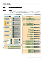
order. These elements are marked as shown in Overview (Page 76).
Note
Latched drive orders are processed separately and are stored as door commands with an
associated door command expansion bit. Any other, unlatched door command apart from
"deenergized" overwrites or clears the latched drive order including the expansion bit.
Logical input signals
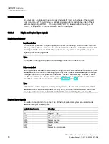
To be able to map internal dependencies in the logic, selected system states are made
available as logical input signals.
Logical signal source
Meaning
Q0
Logical 0 "low"
Q1
Logical 1 "high"
Q33
Motor deenergized
Q34
Motor stopped
Q35
System opened
Q36
System closed
Q37
Fault
Q38
System in normal mode

