Controllers
4.5 Relay and fieldbus interfaces
ATD4xxW Door Controller for Industrial Applications
120
System Manual, 01/2017, A5E38080677-AB
4.5.2.3
Wiring and connecting relay outputs
Wiring
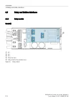
The USS module has 2 relay outputs (closer contact).
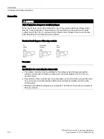
Maximum voltages of 42.0 V (peak value,
≙
29.6 V
rms
in the case of sinusoidal voltage (SELV
according to EN60950-1)) may be applied to the USS module.
Contact rating of the relay outputs:
●
DC max: 30 V DC, 500 mA
●
AC max: 29.6 V AC, 500 mA, sinusoidal (limited due to the fact that only SELV is
permissible on the module)
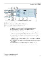
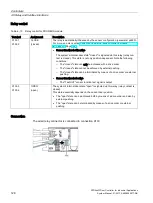
The matching 4-pole mating connector (PHOENIX MC1.5/4-ST-3.81) with the screw
terminals is delivered along with the module (plugged in).
The pin assignments are:
Relay control
Table 4- 7
Relay control for USS module
Terminal
Assignment
Description
X100.1
X100.2
CLOSE
(closed)
The relay is additionally influenced by the sensor configuration (parameter p4600).
See also section Sensors and external sensor interface module (Page 152).
•
Sensor function test inactive
The system's internal door state "closed" is signaled via this relay (relay con-
tact is closed). This state is not only position-dependent. Note the following
conditions:
–
The "closed" state can only be achieved with a drive order.
–
The "closed" state cannot be achieved by external pushing.
–
The "closed" state can be terminated by means of a drive order or external
pushing.
•
Sensor function test active
–
The "TestOUT" sensor function test signal is output.
X100.3
X100.4
OPEN
(open)
The system's internal door state "open" is signaled via this relay (relay contact is
closed).
This state essentially depends on the current door position.
•
The "open" state can be achieved both by means of a drive order and also by
external pushing.
•
The "open" state can be terminated by means of a drive order or external
pushing.


