Controllers
4.5 Relay and fieldbus interfaces
ATD4xxW Door Controller for Industrial Applications
System Manual, 01/2017, A5E38080677-AB
135
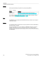
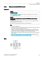
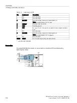
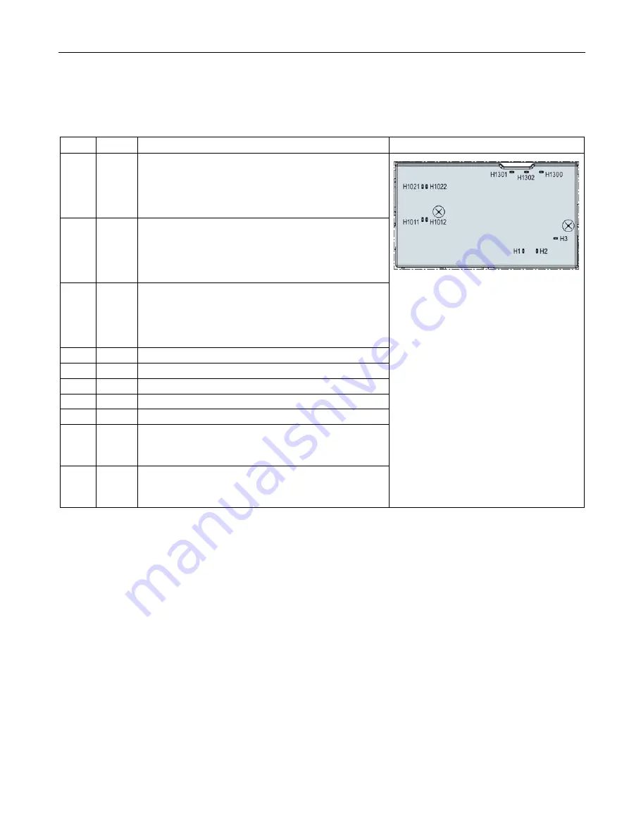
LED signals
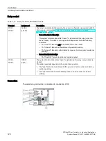
The following five status LEDs are available on the PROFINET module:
LED
Color
Description
Position
H1
Green Relay K1 picked up
LED H1 switches on when the controller has detected the
CLOSED position and the pulse generator ceases to
output pulses. The LED H1 is controlled by the basic
module (signal X200.11).
H2
Green Relay K2 picked up
LED H2 switches on when the current distance of the
door to the OPEN position falls below 2 cm and the relay
has switched on. The LED H2 is controlled by the basic
module (signal X200.9).
H3
Green Valid incoming telegram
LED H3 is controlled by the basic module (signal
X200.12), and indicates the communication status. The
LED flashes to indicate incoming, valid telegrams. Each
signal change stands for such a telegram.
H1011 Green Port 1: LINK
H1012 Orange Port 1: ACT
H1021 Green Port 2: LINK
H1022 Orange Port 2: ACT
H1300 Green Power on
H1301 Red
"Bus error" PROFINET communication disrupted
The H1301 LED flashes red in the event of a PROFINET
communication error.
H1302 Red
"Group error" internal communication disrupted
The H1302 LED flashes red in the event of an internal
communication error.
Network structure/network topologies
The ATD430W IO device supports the star, line, tree and ring structure network topologies.
The IO device has an integrated switch for the line and ring structures. The MRP redundancy
process is used in the case of the ring structure. In this case, the IO device is the MRP client
and cannot be used as the redundancy manager (MRP manager). This must be provided for
separately in the network structure.


