Secondary Tests
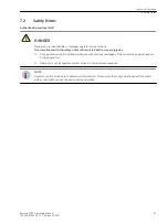
Secondary tests can never replace primary tests because they cannot detect connection faults. They provide a
theoretical check of the setting values only. Please see section 9 of the device manual for further information.
For tests using secondary test equipment, make sure that all necessary input signals are simulated and output
circuits are interrupted, particularly trip and close commands to the circuit‑breakers and other plant unless
that functionality is included in the test.
When testing the device with secondary test equipment, make sure that no other measurement quantities are
connected and that the trip and close circuits to the circuit‑breakers and other primary switches are discon-
nected from the device.
Isolate the auxiliary DC supplies for alarm and tripping from the relay and remove the trip and intertrip links.
Ensure that any essential services that share supplies are not interrupted.
Disconnect communications ports or configure control systems to prepare for the tests.
In
Out of service
mode the output relays will not operate and the serial communications signals will not
be sent over the rear Remote port. In
Test
mode the IEC 61850 signals will be marked as test.
Carry out injection tests for each relay function as required as described in this document.
i
i
NOTE
For all high current tests it must be ensured that the test equipment has the required rating and stability
and that the relay is not stressed beyond its thermal limit. The maximum duration of the current injection
should be limited in case an error is present such that the expected relay operation does not stop the test.
Secondary tests must only be carried out by personnel who are qualified electricians and are familiar with the
commissioning of protection systems, the operation of the system, and with safety regulations and provisions
(switching, grounding, etc.).
Make sure that there are no connections to the primary system during the secondary test. In the secondary
test it is assumed that there are still no connections to the primary system. But if you do this in the primary
system, special safety conditions must be followed. Connection examples for current and voltage transformer
circuits are provided in the device manuals.
Before checking, the user should familiarize themselves with the measuring principle of the protection func-
tion in the Device manual and consider the test recommendations given in the Device manual:
•
Perform the tests using multi-phase test equipment since numerous protection functions require a 3-
phase system.
•
Most protection functions can be tested using stationary signals. Some protection functions require tran-
sient signals. Typical examples are the testing of protection reaction on power swings (power-swing
blocking in distance protection and out-of-step protection) and the transient effect on transformers. They
generate transient test files with a dynamic network calculation program or these test files are provided
by special test programs.
•
If setting values are offered only in percent or per unit, the setting values refer only to rated quantities of
the protected object. Secondary test quantities must be converted using the transformer ratio.
•
Perform the tests successively. Activate only the function that you wish to test. Make use of Reydisp
Manager 2 support.
•
Since protection functions can be assigned to different protection function groups, check the interaction
between function groups as well. If the user has created their own application template or modified the
delivered template, Siemens recommends that they check the interaction. The application templates
provided with the device have been tested.
•
Check the reaction of the protection functions via the indications in the corresponding logs. The indica-
tions in the spontaneous indication log (available in online mode), which are shown at the moment of
occurrence, are a good tool. Testing using the fault record (binary signal traces in relation to the input
variables) is also advisable for transient processes.
6.3
Commissioning
6.3 Secondary Tests
Reyrolle 7SR5, Operating, Manual
85
C53000-B7040-C013-1, Edition 05.2021
Содержание Reyrolle 7SR5
Страница 6: ...6 Reyrolle 7SR5 Operating Manual C53000 B7040 C013 1 Edition 05 2021 ...
Страница 10: ...10 Reyrolle 7SR5 Operating Manual C53000 B7040 C013 1 Edition 05 2021 ...
Страница 40: ...40 Reyrolle 7SR5 Operating Manual C53000 B7040 C013 1 Edition 05 2021 ...
Страница 76: ...76 Reyrolle 7SR5 Operating Manual C53000 B7040 C013 1 Edition 05 2021 ...
Страница 114: ...114 Reyrolle 7SR5 Operating Manual C53000 B7040 C013 1 Edition 05 2021 ...

