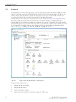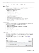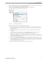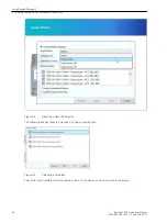
Display of Routings and Status
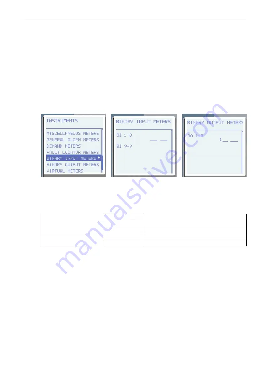
You can route signals from the 7SR5 device matrix to binary inputs and binary outputs. With the menu item
Main Menu > Instruments > Binary Input Meters
on the device you can display the routing of the logical
signals and their status.
In order to display the routings in the 7SR5 device, proceed as follows:
•
In order to access the
Binary IO
from the main menu, use the fascia navigation keys:
Main Menu > Instruments > Binary Input Meters
•
Use the navigation keys of the front fascia to navigate within the displayed list and select one of the 2
following menu entries:
–
Binary inputs
–
Binary outputs
[sc_7SR5_DeviceBinaryInputOutputMenu, 1, --_--]
Figure 4-21
Binary Inputs and Output Menu
All available binary inputs of the 7SR5 device will be displayed.
The following table shows the meaning of the status of the individual menu entries
Binary inputs
and
Binary
outputs
.
Menu Item
Status
Description
Binary input
1
Input is active
–
Input is not active
Binary output
1
Output is active (contact is closed)
–
Output is not active (contact is open)
The status of the respective binary inputs, binary outputs or the LEDs is updated automatically by the actual
state in the device.
•
Use the navigation keys to select the binary input, for example Binary input1.
Configuring Binary Outputs
Any function element in the Output Matrix can be selected to operate any output relay, LED or virtual input/
output.
Functions and signals that initiate operation of each binary output are defined in the
Settings > Configura-
tion > Binary Outputs > Output Matrix
menu. All outputs are fully user configurable from the front fascia
and can be programmed to operate from any or all of the available functions and signals in the output matrix
menu.
shows an assignment to a binary output following the menu steps. The 50-1 overcurrent protec-
tion stage is assigned to BO-1 and LED11.
In the Output Matrix, use the up or down keys to see the required function, then press the Enter button to
configure a binary output, LED or virtual to this signal. Use the right arrow key to proceed to further BOs.
Use the up arrow key by making 1 to map an output, then press the Enter button to confirm your assignment.
4.7
Using the Device Fascia
4.7 Display of Routings and Status
56
Reyrolle 7SR5, Operating, Manual
C53000-B7040-C013-1, Edition 05.2021
Содержание Reyrolle 7SR5
Страница 6: ...6 Reyrolle 7SR5 Operating Manual C53000 B7040 C013 1 Edition 05 2021 ...
Страница 10: ...10 Reyrolle 7SR5 Operating Manual C53000 B7040 C013 1 Edition 05 2021 ...
Страница 40: ...40 Reyrolle 7SR5 Operating Manual C53000 B7040 C013 1 Edition 05 2021 ...
Страница 76: ...76 Reyrolle 7SR5 Operating Manual C53000 B7040 C013 1 Edition 05 2021 ...
Страница 114: ...114 Reyrolle 7SR5 Operating Manual C53000 B7040 C013 1 Edition 05 2021 ...


