background image

[sc_7SR5_SecurityLogOperationPanel, 1, --_--]

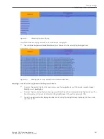
Figure 9-9

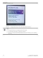
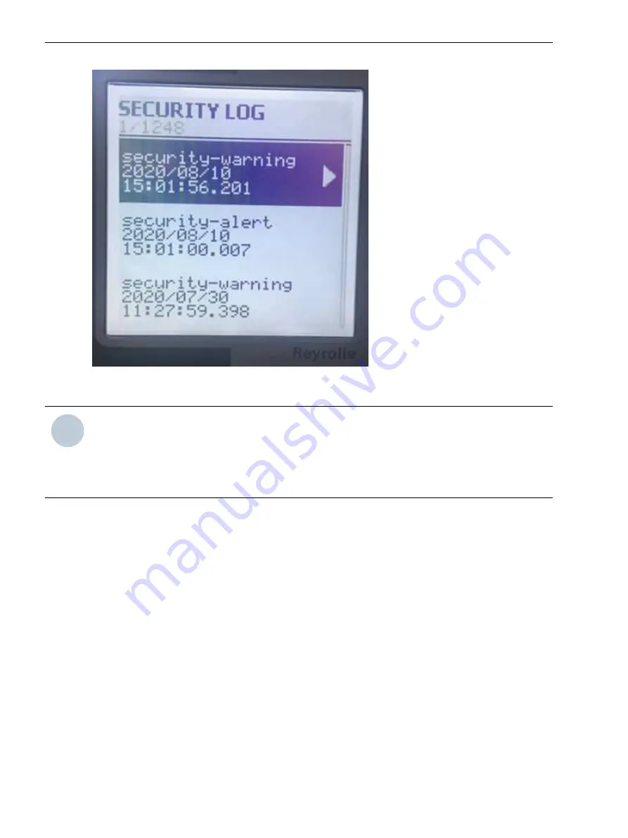
Reading the Security Log on the On-Site Operation Panel of the Device

i

i

NOTE

The logged indications are preconfigured and cannot be changed!

You cannot delete the log which is organized as a ring buffer.

If you want to archive security-relevant information without loss of information, you must regularly

read this log.

Security Settings

9.9 Recording of Cyber-Security Events

146

Reyrolle 7SR5, Operating, Manual

C53000-B7040-C013-1, Edition 05.2021

Содержание Reyrolle 7SR5

Страница 1: ...53000 B7040 C013 1 Preface Table of Contents First Steps 1 Installing the Devices 2 Handling of the Device 3 Using the Device Fascia 4 Using Reydisp Manager 2 5 Commissioning 6 In Service Operation 7 Device Maintenance 8 Security Settings 9 ...

Страница 2: ... of further development of the products The requested performance features are binding only when they are expressly agreed upon in the concluded contract Document version C53000 B7040 C013 1 01 Edition 05 2021 Version of the product described V02 21 Copyright Copyright Siemens 2021 All rights reserved The disclosure duplication distribution and editing of this document or utilization and communica...

Страница 3: ...ion system engineers commissioning engineers persons entrusted with the setting testing and maintenance of automation selective protection and control equipment and operational crew in electrical installations and power plants Scope This manual applies to the Reyrolle 7SR5 device family Further Documentation dw_7SR5_furtherdocumentation_operatingmanual 3 en_US Reyrolle 7SR5 Operating Manual 3 C530...

Страница 4: ...al steps when engineering with Reydisp Manager 2 In addi tion the engineering guide shows you how to load a planned configuration to a Reyrolle 7SR5 device and update the functionality of the Reyrolle 7SR5 device Virtual Relay The virtual relay allows a user to view control and manipulate a virtual Reyrolle 7SR5 device The virtual relay is a tool that can facilitate training and understanding of t...

Страница 5: ... all instructions in order to avoid death or severe injuries CAUTION CAUTION means that medium severe or slight injuries can occur if the specified measures are not taken Comply with all instructions in order to avoid moderate or minor injuries NOTICE NOTICE means that property damage can result if the measures specified are not taken Comply with all instructions in order to avoid property damage ...

Страница 6: ...6 Reyrolle 7SR5 Operating Manual C53000 B7040 C013 1 Edition 05 2021 ...

Страница 7: ...dication and Control 47 4 4 Structure of the Menu 51 4 5 Menu Tree 52 4 6 Notification and Dialog Windows 55 4 7 Display of Routings and Status 56 5 Using Reydisp Manager 2 59 5 1 General 60 5 2 Operator Actions in the Offline and Online Area 62 5 3 Transmitting the Configuration to a 7SR5 Device for the First Time 68 5 4 Transferring Device Data from the Device to the PC 72 5 5 Retrieving Fault R...

Страница 8: ...ith Reydisp Manager 2 104 7 4 5 Reading Fault Data from the HMI Screen 105 7 4 6 Reading Fault Data from the PC with Reydisp Manager 2 107 7 5 Instruments and Meters 109 7 5 1 Overview of Measured and Metered Values 109 7 5 2 Reading Instrument Values from the Device Fascia HMI screen 109 7 5 3 Reading Instrument Values from Reydisp Manager 2 110 8 Device Maintenance 115 8 1 Execute Checks 116 8 2...

Страница 9: ...5 9 3 Security Settings in the Device 136 9 4 Device Access Security 137 9 5 Connection Password 138 9 6 Maintenance Password Configuration 139 9 7 Authentication Connection Password and Confirmation ID During Operation 140 9 8 Resetting and Deactivating the Passwords 141 9 9 Recording of Cyber Security Events 142 Table of Contents Reyrolle 7SR5 Operating Manual 9 C53000 B7040 C013 1 Edition 05 20...

Страница 10: ...10 Reyrolle 7SR5 Operating Manual C53000 B7040 C013 1 Edition 05 2021 ...

Страница 11: ...First Steps 1 1 Unpacking Repacking Returning and Storing 12 1 2 Incoming Inspection 14 1 3 Electrical Inspection 15 1 Reyrolle 7SR5 Operating Manual 11 C53000 B7040 C013 1 Edition 05 2021 ...

Страница 12: ...Enclose the accessories supplied and the test certificate in the package with the device Returning a Device Return devices to the manufacturer stating the defect Use the original packaging or transport packaging where possible Send damaged devices to the following address Siemens AG EM DG PRO MF Rückwaren Rohrdamm 7 13629 Berlin Germany Protect the optical interfaces on the communication modules a...

Страница 13: ...capacitors to form on the printed circuit board assemblies again If devices are to be shipped elsewhere you can reuse the transport packaging Storage packing of the individual devices is not adequate for transport purposes First Steps 1 1 Unpacking Repacking Returning and Storing Reyrolle 7SR5 Operating Manual 13 C53000 B7040 C013 1 Edition 05 2021 ...

Страница 14: ...erforming a Follow Up Inspection on a Device Visually check for external damage as soon as you have unpacked the devices they must not show any signs of dents or cracks Checking the Rated Data and Functions Check the rated data and functions using the complete order designation the product code The device manual contains all technical data and a description of the functions Check the information p...

Страница 15: ...nnected to the main panel earth Connecting a Device Connect all cables and lines Use the connection diagrams in the Hardware and Device manuals Use the screws provided Tighten the terminal screws The rear terminal blocks comprise M4 female terminals for wire connec tions Each terminal can accept 2 x M4 diameter crimps Safety Notes DANGER Danger during electrical inspection Noncompliance with the s...

Страница 16: ...fails to power on pack this device and return it to the manufacturer stating the defect COM 1 port RS485 Block A and X1 Terminals connection to this communication facility is by screened twisted pair cable On site when wiring other facilities ensure that these terminals are not obscured by other wiring runs Cable should be RS485 compliant Laser class 1 is maintained in compliance with EN 60825 1 a...

Страница 17: ...Installing the Devices 2 1 Device Dimensions and Drilling Drawings 18 2 2 Installing Devices 20 2 3 Connections and Earthing 22 2 Reyrolle 7SR5 Operating Manual 17 C53000 B7040 C013 1 Edition 05 2021 ...

Страница 18: ...ings dw_7SR5_E6_dimensions 4 en_US Figure 2 1 Size 6 Case Overall Dimensions and Panel Drilling 2 1 Installing the Devices 2 1 Device Dimensions and Drilling Drawings 18 Reyrolle 7SR5 Operating Manual C53000 B7040 C013 1 Edition 05 2021 ...

Страница 19: ...imensions 4 en_US Figure 2 2 Size 12 Case Overall Dimensions and Panel Drilling Installing the Devices 2 1 Device Dimensions and Drilling Drawings Reyrolle 7SR5 Operating Manual 19 C53000 B7040 C013 1 Edition 05 2021 ...

Страница 20: ...ssembly opening is prepared then cut out the required assembly opening Produce the holes as shown in the drilling plan Fitting Devices Insert the device in the installation opening Make sure that the fastening screws of the on site operation panels also protrude exactly into the openings Secure the device to the panel at the top and bottom using the M4 machine screws lock washers and nuts provided...

Страница 21: ...onsists of 28 x M4 8 mm screws 28 x M4 lock washers i i NOTE Fixing kits are not supplied for unused terminal blocks refer to the wiring diagram for the number of blocks used Installing the Devices 2 2 Installing Devices Reyrolle 7SR5 Operating Manual 21 C53000 B7040 C013 1 Edition 05 2021 ...

Страница 22: ...trolytic capacitors to form on the printed circuit board assemblies again The case earth stud should be solidly earthed to the panel earth Terminal B28 power supply unit should be connected to the case earth stud A minimum wire size of 2 5 mm2 is recommended Connecting Devices Connect all cables and leads Use the connection diagrams in the Hardware and Device manuals Earthing the Device Join sever...

Страница 23: ...Handling of the Device 3 1 Case and Element 24 3 2 Withdrawing the Device Element 32 3 Reyrolle 7SR5 Operating Manual 23 C53000 B7040 C013 1 Edition 05 2021 ...

Страница 24: ...e and Element Size 6 Case and Device sc_7SR5_size6_FrontPhoto 1 _ Figure 3 1 Front View 3 1 Handling of the Device 3 1 Case and Element 24 Reyrolle 7SR5 Operating Manual C53000 B7040 C013 1 Edition 05 2021 ...

Страница 25: ... sc_7SR5_size6_FrontPhotoRightView 1 _ Figure 3 2 Right View Handling of the Device 3 1 Case and Element Reyrolle 7SR5 Operating Manual 25 C53000 B7040 C013 1 Edition 05 2021 ...

Страница 26: ... sc_7SR5_size6_front angle 1 _ Figure 3 3 Left View Handling of the Device 3 1 Case and Element 26 Reyrolle 7SR5 Operating Manual C53000 B7040 C013 1 Edition 05 2021 ...

Страница 27: ... sc_7SR5_size6_labelView 1 _ Figure 3 4 Label View Handling of the Device 3 1 Case and Element Reyrolle 7SR5 Operating Manual 27 C53000 B7040 C013 1 Edition 05 2021 ...

Страница 28: ..._rear 1 _ Figure 3 5 Rear View Device fitted with optical LC ports RS485 2 part connector shown fitted Handling of the Device 3 1 Case and Element 28 Reyrolle 7SR5 Operating Manual C53000 B7040 C013 1 Edition 05 2021 ...

Страница 29: ... sc_7SR5_size12_FrontPhoto 1 _ Figure 3 6 Front View sc_7SR5_size12_TopRightFrontView 1 _ Figure 3 7 Right View Handling of the Device 3 1 Case and Element Reyrolle 7SR5 Operating Manual 29 C53000 B7040 C013 1 Edition 05 2021 ...

Страница 30: ...e12_TopLeftFrontView 1 _ Figure 3 8 Left View sc_7SR5_size12_LeftSideView 1 _ Figure 3 9 Label View Handling of the Device 3 1 Case and Element 30 Reyrolle 7SR5 Operating Manual C53000 B7040 C013 1 Edition 05 2021 ...

Страница 31: ...RearView 1 _ Figure 3 10 Rear View Device fitted with RJ45 ports RS485 2 part connector shown not fitted Handling of the Device 3 1 Case and Element Reyrolle 7SR5 Operating Manual 31 C53000 B7040 C013 1 Edition 05 2021 ...

Страница 32: ...n links The removed device should not be carried using the fascia levers it should be held by the top and bottom plates and exposed PCB s should not be touched The device should be protected from damage handled with care and not exposed to contamination The device should be re inserted into the case without the use of excessive force sc_7SR5_size6_RetainingScrew 1 en_US Figure 3 11 Retaining Screw...

Страница 33: ...R5_size6_LooseningScrews 1 _ Figure 3 12 Screws Loosened and Handles Pulled Out Handling of the Device 3 2 Withdrawing the Device Element Reyrolle 7SR5 Operating Manual 33 C53000 B7040 C013 1 Edition 05 2021 ...

Страница 34: ..._TopViewPartWithdrawn 1 _ Figure 3 13 Top View Device Partially Withdrawn from the Case Handling of the Device 3 2 Withdrawing the Device Element 34 Reyrolle 7SR5 Operating Manual C53000 B7040 C013 1 Edition 05 2021 ...

Страница 35: ...evice Partially Withdrawn from the Case sc_7SR5_size6_RearViewFullyWithdrawn 1 _ Figure 3 15 Rear View Device Fully Withdrawn from the Case Handling of the Device 3 2 Withdrawing the Device Element Reyrolle 7SR5 Operating Manual 35 C53000 B7040 C013 1 Edition 05 2021 ...

Страница 36: ...ied using the fascia levers it should be held by the top and bottom plates and exposed PCB s should not be touched The device should be protected from damage handled with care and not exposed to contamination The device should be re inserted into the case without the use of excessive force sc_7SR5_size6_RetainingScrew 1 en_US Figure 3 16 Retaining Screw i i NOTE Remove RS485 connector and ethernet...

Страница 37: ...2_TopViewPartWithdrawn 1 _ Figure 3 18 Top View Device Partially Withdrawn from the Case Handling of the Device 3 2 Withdrawing the Device Element Reyrolle 7SR5 Operating Manual 37 C53000 B7040 C013 1 Edition 05 2021 ...

Страница 38: ...FrontViewPartWithdrawn 1 _ Figure 3 19 Front View Device Partially Withdrawn from the Case Handling of the Device 3 2 Withdrawing the Device Element 38 Reyrolle 7SR5 Operating Manual C53000 B7040 C013 1 Edition 05 2021 ...

Страница 39: ..._FrontViewFullyWithdrawn 1 _ Figure 3 20 Front View Device Fully Withdrawn from the Case Handling of the Device 3 2 Withdrawing the Device Element Reyrolle 7SR5 Operating Manual 39 C53000 B7040 C013 1 Edition 05 2021 ...

Страница 40: ...40 Reyrolle 7SR5 Operating Manual C53000 B7040 C013 1 Edition 05 2021 ...

Страница 41: ...ements and Display Elements 43 4 3 Displays for Indication and Control 47 4 4 Structure of the Menu 51 4 5 Menu Tree 52 4 6 Notification and Dialog Windows 55 4 7 Display of Routings and Status 56 4 Reyrolle 7SR5 Operating Manual 41 C53000 B7040 C013 1 Edition 05 2021 ...

Страница 42: ...ation of settings Resetting saved information Showing default and control displays measured values and logs Executing switching operations with large graphical HMI screen Initiating configured actions via function keys Binary output test from Maintenance menu Status display with LED Function configuration Configuring inputs outputs and LEDs CT VT configuration Setting serial communication paramete...

Страница 43: ...ascia 1 LCD 2 Push buttons 3 USB port cover 4 Withdrawal lever 5 Device identification number 6 Transparent LED label door 7 28 3 colored LEDs 4 2 Using the Device Fascia 4 2 Overview of Operator Elements and Display Elements Reyrolle 7SR5 Operating Manual 43 C53000 B7040 C013 1 Edition 05 2021 ...

Страница 44: ...creen 3 second delay LED test reset Figure 4 6 Fascia Enter Button Enter key used to initiate and accept settings changes Figure 4 7 Fascia Cancel Button Cancel key used to cancel settings changes and or move up the menu structure by one level per press Figure 4 8 USB Port Cover USB port to connect to other devices e g laptop Figure 4 9 Withdrawal Lever 2 levers are located on the front of the rel...

Страница 45: ...e in 2 lines of 14 The left hand line of LEDs are numbered 1 to 14 from top to bottom The right hand line of LEDs are numbered 15 to 28 from top to bottom Figure 4 13 Fascia Function 1 Button Binary input Function button 1 Figure 4 14 Fascia Function 0 Button Binary input Function button 0 Using the Device Fascia 4 2 Overview of Operator Elements and Display Elements Reyrolle 7SR5 Operating Manual...

Страница 46: ...mentation Refer to device documentation Product information Device manual Hardware manual Operating manual and Communication protocol manuals Electrostatic Sensitive Devices warning Using the Device Fascia 4 2 Overview of Operator Elements and Display Elements 46 Reyrolle 7SR5 Operating Manual C53000 B7040 C013 1 Edition 05 2021 ...

Страница 47: ...increase or decrease the contrast The backlight brightness adjusted by pressing the Enter and Cancel pushbuttons together then pressing the right arrow pushbutton to select brightness and then using the or keys to increase or decrease the level To conserve power the display backlighting is extinguished when no buttons are pressed for a user defined period The Backlight Timer setting within the Con...

Страница 48: ...will display the primary current default screen display image see Figure 4 18 after sending configuration to the device if no user HMI screens have been configured Using the Device Fascia 4 3 Displays for Indication and Control 48 Reyrolle 7SR5 Operating Manual C53000 B7040 C013 1 Edition 05 2021 ...

Страница 49: ...rameterized sequence by pressing the fascia navigation button right arrow Control Displays The 7SR5 device graphic display can be configured to show a mimic of the associated plant by using the Reymimic editor in Reydisp Manager 2 The control displays can graphically and dynamically update the switch position of switching objects In addition control displays offer you the possibility of selecting ...

Страница 50: ...le displays the Navigation right arrow buttons is used to display the different screens If several controllable objects exist on a single screen pressing Enter and using the up or down keys allows the user to toggle between different objects After pressing function key 1 or function key 0 a confirmation screen appears to activate the control function Control mode is reset after a switching procedu...

Страница 51: ...enu displays the current values status of binary inputs and binary outputs The following meters are available and can be navigated by using the and TEST RESET keys See section 8 1 in the device manual for further information Fault Data Mode The 7SR5 stores a maximum of 100 relay trip fault records Each stored fault data can be viewed by pressing the Test Reset key Each record contains data of the ...

Страница 52: ...he Settings menu relay settings CT VT configuration inputs outputs are available and function configuration can be selected Binary outputs can be tested from the Maintenance menu and the serial RS 485 port communication settings are available in the Communications submenu Instruments Menu In the Instruments menu you can display various real time measured values from analogue inputs and the status ...

Страница 53: ...tate Security Log Menu The Security Log menu lists the events associated with the security access to the device and are categorized as Events or Alarms These can be viewed by entering the Security ID if it has been configured in the device configu ration using Reydisp Manager Control Mode Menu The Control Mode menu shows controllable plant items that have been included by the user in the configura...

Страница 54: ... Device Information menu offers you detailed information about the device such as the firmware version serial number etc Using the Device Fascia 4 5 Menu Tree 54 Reyrolle 7SR5 Operating Manual C53000 B7040 C013 1 Edition 05 2021 ...

Страница 55: ...viceNotificationWindows 1 _ Figure 4 20 Examples of Notification Windows Dialogs Dialogs are interactive notification windows in the base bar In the dialogs you are prompted to actively carry out actions You confirm the context dependent command prompts offered here by pressing the softkeys below the prompts 4 6 Using the Device Fascia 4 6 Notification and Dialog Windows Reyrolle 7SR5 Operating Ma...

Страница 56: ...tus of the respective binary inputs binary outputs or the LEDs is updated automatically by the actual state in the device Use the navigation keys to select the binary input for example Binary input1 Configuring Binary Outputs Any function element in the Output Matrix can be selected to operate any output relay LED or virtual input output Functions and signals that initiate operation of each binary...

Страница 57: ...22 Binary Output Menu Steps Output Matrix Test sc_7SR5_DeviceOutputMatrixTestSteps 1 _ Figure 4 23 Output Matrix Test Steps Using the Device Fascia 4 7 Display of Routings and Status Reyrolle 7SR5 Operating Manual 57 C53000 B7040 C013 1 Edition 05 2021 ...

Страница 58: ...d to any binary output In the Output Matrix Test menu view the signals with the down arrow key Press the Enter button to perform a test in this signal then after a confirmation page choose Yes with the up or down key and the press Enter The configured binary output will close sc_7SR5_DeviceOutputMatrixTestCompleted 1 _ Figure 4 24 Output Matrix Test Completed Using the Device Fascia 4 7 Display of...

Страница 59: ...ne and Online Area 62 5 3 Transmitting the Configuration to a 7SR5 Device for the First Time 68 5 4 Transferring Device Data from the Device to the PC 72 5 5 Retrieving Fault Records and Log Contents 74 5 Reyrolle 7SR5 Operating Manual 59 C53000 B7040 C013 1 Edition 05 2021 ...

Страница 60: ...p Manager 2 Reydisp Manager 2 uses templates to update and configure 7SR5 devices The templates need to be installed in Reydisp Manager for any required device type and version All device templates must be installed separately for the required PC software and device type Template installers are also available to download from the Siemens web page e g 7SR5_DeviceFW V2 10CFG V2 10_RDT V2 10 exe sc_7...

Страница 61: ...e thermal curves Configure serial communication data points and fascia event log Edit IEC 61850 Stations using the optional System Configurator with seamless integration with Digsi Using Reydisp Manager 2 5 1 General Reyrolle 7SR5 Operating Manual 61 C53000 B7040 C013 1 Edition 05 2021 ...

Страница 62: ...a can be transferred to the device using an online connection and perform the following tasks when there is a physical connection between Reydisp Manger 2 and a 7SR5 device Sending device configuration Retrieve device data such as event logs fault logs and waveform fault records Retrieve device configuration Set device date and time Displaying selected analogue measured values Protection setting p...

Страница 63: ... The product code can be entered directly into the Device MLFB user entry box as a partial code or complete code and the selection will be filtered automatically to assist the selection If the device is connected to the PC by USB cable the product code can be provided from the device using the From Connected Device option This can be used to get the product code from a connected device and proceed...

Страница 64: ... step by step sc_7SR5_ReydispManager2SelectTemplate 2 _ Figure 5 5 Selecting a Template Select the relay firmware version and give a name to the device as a device name in the project Using Reydisp Manager 2 5 2 Operator Actions in the Offline and Online Area 64 Reyrolle 7SR5 Operating Manual C53000 B7040 C013 1 Edition 05 2021 ...

Страница 65: ...ydispManager2DeviceName 1 _ Figure 5 7 Entering the Device Name Enter an IED name for using in the IEC 61850 project and select the IEC 61850 edition Using Reydisp Manager 2 5 2 Operator Actions in the Offline and Online Area Reyrolle 7SR5 Operating Manual 65 C53000 B7040 C013 1 Edition 05 2021 ...

Страница 66: ...electIECEdition 1 _ Figure 5 8 Entering IED Name and Selecting IEC 61850 Edition Using Reydisp Manager 2 5 2 Operator Actions in the Offline and Online Area 66 Reyrolle 7SR5 Operating Manual C53000 B7040 C013 1 Edition 05 2021 ...

Страница 67: ... 1 _ Figure 5 9 Device Construction Click the Finish button after the device creation is complete Using Reydisp Manager 2 5 2 Operator Actions in the Offline and Online Area Reyrolle 7SR5 Operating Manual 67 C53000 B7040 C013 1 Edition 05 2021 ...

Страница 68: ... software In Reydisp Manager 2 initialization with a configuration associates the offline configuration with the 7SR5 device For this the 7SR5 device transmits its serial number which is then entered in the corresponding offline configuration sc_7SR5_SendDeviceConfiguration 1 _ Figure 5 10 Send Device Configuration In the project tree select the device of the offline configuration and in the devic...

Страница 69: ...to a relay proceed with Connect by USB in communication settings dw_7SR5_communication_to_front_USB_port 1 en_US Figure 5 12 Front USB Connection The front USB port for local connection Standard with a cover provides environmental protection The device functions can be set on a PC using Reydisp Manager 2 software via the relay USB port by a standard USB cable Using Reydisp Manager 2 5 3 Transmitti...

Страница 70: ...2 and Channel 2 Terminal Reference X3 or 2 optical LC ethernet ports Channel 1 Terminal Reference X4 and Channel 2 Terminal Reference X5 The Ethernet port is unconfigured by default IP addresses can be entered manually via the Configure Inter face menu in Tasks by the user IEC 61850 HSR PRP and RSTP operation Remote access to Reydisp Manager If a device IP address assigned to an Ethernet port from...

Страница 71: ...ngs to the device Reydisp Manager 2 checks that the settings are compatible with the designated device If they are incompatible the settings are not uploaded to the device There will be warning messages displayed in red on the information window without the word Complete The user should check these incompatible settings Using Reydisp Manager 2 5 3 Transmitting the Configuration to a 7SR5 Device fo...

Страница 72: ...e as the default name sc_7SR5_GetDeviceData 1 _ Figure 5 15 Get Device Data Once Get Device Data has been selected the device data can be retrieved from the device A connection window is provided to select between the default USB connection method or connecting via the rear Ethernet port using the IP address of the device The connection type to the device can be selected and the Next button clicke...

Страница 73: ...hat are read from the device All entries can be archived as files which can be used in further applications The file name can be changed by the user by a right click of the mouse on the waveform record and entering the preferred name followed by Apply Using Reydisp Manager 2 5 4 Transferring Device Data from the Device to the PC Reyrolle 7SR5 Operating Manual 73 C53000 B7040 C013 1 Edition 05 2021...

Страница 74: ...a window to open the data content sc_7SR5_DeviceDataTab 1 _ Figure 5 18 Device Data Window The waveform display window will open as illustrated in Figure 5 19 sc_7SR5_WaveformDisplay 1 _ Figure 5 19 Waveform Display 5 5 Using Reydisp Manager 2 5 5 Retrieving Fault Records and Log Contents 74 Reyrolle 7SR5 Operating Manual C53000 B7040 C013 1 Edition 05 2021 ...

Страница 75: ...ow The Event Log Viewer window will open and any time tagging of any change of state Event in the relay can be seen As an event occurs the actual event condition is logged as a record along with a time and date stamp to a resolution of 1 millisecond When a starter picks up raised and sometime later drops off cleared In summary a one stage event is Raised only a two stage event maybe Raised or Clea...

Страница 76: ...76 Reyrolle 7SR5 Operating Manual C53000 B7040 C013 1 Edition 05 2021 ...

Страница 77: ...Commissioning 6 1 Overview 78 6 2 Initial Startup 80 6 3 Secondary Tests 85 6 4 Primary Tests 87 6 5 Device Configuration 88 6 Reyrolle 7SR5 Operating Manual 77 C53000 B7040 C013 1 Edition 05 2021 ...

Страница 78: ...ctly configured Check that it is fully inserted into the case Ensure that the device is grounded from the earthing points correctly Hardware Tests Operation of all inputs and outputs are tested in the factory Tests can be repeated to check the device opera tion in its intended application or by simple direct operation tests as described in this section The status indications of the respective bina...

Страница 79: ...afely Routine Maintenance The device does not require scheduled preventative maintenance although some users apply periodic checking schedules to all protection devices Operational checking can be limited to periodic visual checks of measured analogue values at the device instruments or the data provided over the communications channels to supplement the continuous self checking features of the de...

Страница 80: ... the relay operates and an Edit View Settings Group which is visible on the display and which can be changed from the fascia keys This allows the settings in 1 group to be altered from the relay fascia while the protection continues to operate on a different unaffected group The Active Settings Group and the Edit Settings Group are selected in the Configuration Device menu The currently Active Gro...

Страница 81: ...ethernet port for data to be trans ferred to the PC online If there is a communication connection to systems control measured values that the operational crew can verify are also transmitted here by rear ethernet communication The device is able to indicate the measurand values from Reydisp Manager 2 software with connection by COM 2 using the front USB port which has the IP address 192 168 2 1 or...

Страница 82: ...168 2 1 should be typed for the USB front port connection or user defined IP address for the rear ethernet port connection to the IP Address box The user can then click the Create button and select connection then click the Connect button to open the Relay Monitor Tool Commissioning 6 2 Initial Startup 82 Reyrolle 7SR5 Operating Manual C53000 B7040 C013 1 Edition 05 2021 ...

Страница 83: ...ing this signal to the right side main window then releasing the mouse button Several signals can be dragged to the main window on the right and provide continuous monitoring of the measurands Alternatively the measurands could be deleted and removed from the main window by clicking the X symbol on the right side of the window Several measured value windows are preadjustable by adding relevant mea...

Страница 84: ... sc_7SR5_RelayMonitorTool 1 _ Figure 6 4 Relay Monitor Tool Commissioning 6 2 Initial Startup 84 Reyrolle 7SR5 Operating Manual C53000 B7040 C013 1 Edition 05 2021 ...

Страница 85: ...n the secondary test it is assumed that there are still no connections to the primary system But if you do this in the primary system special safety conditions must be followed Connection examples for current and voltage transformer circuits are provided in the device manuals Before checking the user should familiarize themselves with the measuring principle of the protection func tion in the Devi...

Страница 86: ...he test editor using signals from test equipment or the internal signal generator sequences Examine the test sequence in the characteristic curve of the protection function and its spontaneous indications Commissioning 6 3 Secondary Tests 86 Reyrolle 7SR5 Operating Manual C53000 B7040 C013 1 Edition 05 2021 ...

Страница 87: ...test connections between the current transformer and the power transformer windings Primary injection is needed however to verify the polarity of the CTs In these circumstances primary current must be injected through the associated power transformer winding It may be necessary to short circuit another winding in order to allow current to flow During these primary injection tests the injected curr...

Страница 88: ... default option is to use the time from the PC as the source but an option is also available to manually enter a preferred time and date sc_7SR5_SetDateTime 1 _ Figure 6 5 Set Device Date Time The window also includes the connection options available with the default connection selected as a direct connection from the PC to the front USB port and an option to select an IP address for ethernet conn...

Страница 89: ...set This is only applicable for Ethernet communication By default the relay is set to GMT with no daylight saving offset specified To set the Ethernet timezone in the device configuration the user must select the following icon The Edit Timezone dialogue window will appear for editing as required by the system application Clicking Apply will apply the new timezone to the device in the project 6 5 ...

Страница 90: ...r Time The time daylight savings ends Changing the Language on the Device Display The language of the text displayed on the device LCD can be selected and supports multi language capability To reach the language selection menu go to Main Menu Settings Configuration Device and select Language Setting Press the Enter button to change language then by using buttons select the desired language from th...

Страница 91: ...e the confirmation ID is transmitted in an encrypted way to the 7SR5 device where it is checked Authorization for security relevant operations on the device directly via the fascia or Reydisp Manager 2 is assured by the assignment of confirmation IDs These confirmation IDs are assigned exclusively using Reydisp Manager 2 You can find more information in the Security Manual To reach the menu for th...

Страница 92: ...ice fascia The Control ID is set in Reydisp Manager Configuration Device Control Confirmation ID Set Settings changes can only be made at the device fascia after the Setting ID code is entered The Control ID will timeout 60 minutes after the last key press or if the Control ID is entered A user identifier code is required for settings changes at the device security log The Security Log Confirmatio...

Страница 93: ...communication connection to a substation automation technology The communication protocols IEC 60870 5 103 IEC 61850 DNP3 Modbus RTU and Modbus TCP can be used for switching the settings groups A settings group includes all switchable settings of the device Except for a few exceptions for example general device settings such as rated frequency all device settings can be switched sc_7SR5_SettingsGr...

Страница 94: ...rom Configuration User Settings Configuration Binary Inputs Input Matrix sc_7SR5_SettingsGroupChange 1 _ Figure 6 14 Settings Group Change via Binary Inputs Changing Setting Groups via Communication Protocols The communication protocols IEC 60870 5 103 IEC 61850 DNP3 Modbus RTU and Modbus TCP can be used for switching the settings groups via a communication connection See relevant Communication an...

Страница 95: ...n Service Operation 7 1 Overview 96 7 2 Safety Notes 97 7 3 Operation Options 98 7 4 Indications 102 7 5 Instruments and Meters 109 7 Reyrolle 7SR5 Operating Manual 95 C53000 B7040 C013 1 Edition 05 2021 ...

Страница 96: ... The user must be familiar with the principles of operation according to chapter 5 Using Reydisp Manager 2 and chapter 4 Using the Device Fascia Take note that the examples shown are general examples and in terms of wording and detail can vary on the given device depending on variant and configured functional scope Please refer to the respective device manual for the process data that your device ...

Страница 97: ...ians with precise knowledge of the system may operate devices during operation Please carry out all operator control actions in the indicated sequence i i NOTE Operator control actions are Confirmation ID protected This ensures that only operational staff members with access rights can use the device during operation 7 2 In Service Operation 7 2 Safety Notes Reyrolle 7SR5 Operating Manual 97 C5300...

Страница 98: ... query is auto matically terminated Every action carried out within these times restarts the time After a confirma tion query has ended you must confirm changes in device settings again by entering confirmation IDs Before modified settings or the activation of control commands is accepted there will be additional requests to enter the confirmation ID You acknowledge these requests directly on the ...

Страница 99: ...USB or IP address from the rear port in the Communication Settings window and click the Next button Click the Finish button after device is created sc_7SR5_CreatingADeviceWindow 1 _ Figure 7 2 Creating Device Windows Select the device from the project tree on the left The basic information is displayed below the device You can find the following tabs in the menu item Device Information Device info...

Страница 100: ...tensive changes in configurations and setting parameters i i NOTE For a device to be editable offline you must first have created it in a project After successful loading of the configuration the device restarts automatically Procedure From the project tree select the project containing the device to be operated Select the respective device within the project Open the related menu on the right sid...

Страница 101: ...of components of the on site operation panel and of navigation in the device menu tree in chapter 4 Using the Device Fascia In Service Operation 7 3 Operation Options Reyrolle 7SR5 Operating Manual 101 C53000 B7040 C013 1 Edition 05 2021 ...

Страница 102: ...ng a supply voltage failure recorded data are securely held by means of storage in the memory You can read and analyze the log from the device with Reydisp Manager 2 The device display and navigation using keys allow you to read and analyze the logs on site Indications can be output spontaneously via the communication interfaces of the device and through external request via general interrogation ...

Страница 103: ... text displayed in the event log can be edited in the Display Name window of the event filter config uration After completing any filtering and editoring required the file is saved as part of the device configuration and will be sent when the configuration is sent to the device After sending the configuration to the device selected events are shown in the front fascia HMI display event log list Th...

Страница 104: ...ype to the device and click the Next button to start getting device data read from the device sc_7SR5_GetDeviceDataWindow 1 _ Figure 7 6 Get Device Data Once complete available data files will be stored under the Device Data tab that are read from the device All entries are archived and can be used with further applications To open data content the user can select and double click on the available...

Страница 105: ... status at the time of recording and the fault currents Available fault data is displayed in Main Menu Fault Data in date and time format The number of faults stored is shown on the top of the LCD If no faults have been stored the display will indi cate No Faults to display Previous fault data records are stored with actual LEDs status The fault data is displayed in date time order with the most r...

Страница 106: ...ures Trip Alert must be enabled from Device settings in the Configuration menu i i NOTE LEDs will remain illuminated when viewing other screens if the fault screen has not been acknowledged These displays remain stored in the device until manual acknowledgment or release by LED reset In Service Operation 7 4 Indications 106 Reyrolle 7SR5 Operating Manual C53000 B7040 C013 1 Edition 05 2021 ...

Страница 107: ...ice Data tab Select and double click on the available log from the Device Data tab Click Fault Log from Device Fault Logs or click Waveform records from the Waveform Records menu to open data content The available logs display window will open as illustrated in Figure 7 10 7 4 6 In Service Operation 7 4 Indications Reyrolle 7SR5 Operating Manual 107 C53000 B7040 C013 1 Edition 05 2021 ...

Страница 108: ...aining the Analogue Channels Digital Channels and All Channels Users can create new views or modify existing views edit the analogue channel information and format the display using the View Properties command In Service Operation 7 4 Indications 108 Reyrolle 7SR5 Operating Manual C53000 B7040 C013 1 Edition 05 2021 ...

Страница 109: ... display or with Reydisp Manager 2 Reading Instrument Values from the Device Fascia HMI screen You can read measured and metered values on the device display For the display the measured values of a device are summed up in the following groups Operational measured values Fundamental and symmetrical components Function specific measured values Minimum values maximum values average values Energy met...

Страница 110: ...rnet communication The device is able to indicate the measurand values from Reydisp Manager 2 with connection by a COM 2 front USB port with the IP address 192 168 2 1 or user configured IP address from rear ethernet ports Elec trical or LC optical sc_7SR5_InstrumentMonitor 1 _ Figure 7 12 Opening the Relay Monitor Tool Click on the Connect by USB button to connect through a USB front port or type...

Страница 111: ... right side main window then releasing the mouse button Newled3MEAS are analogue signals Newled3CTRL are digital signals Several signals can be dragged on to the main window on the right and provide continuous monitoring of the measurands Alternatively the measurands can be deleted and removed from the main window by clicking the X symbol on the right side Several measured value windows are preadj...

Страница 112: ...EAS I_MSQI1 SeqA C1 Current MEAS I_MSQI1 SeqA C2 Current MEAS I_MSQI1 SeqA C3 Voltage Measure ments Vab MEAS VI_MMXU1 PPV phsAB Vbc MEAS VI_MMXU1 PPV phsBC Vca MEAS VI_MMXU1 PPV phsCA Va MEAS VI_MMXU1 PhV phsA Vb MEAS VI_MMXU1 PhV phsB Vc MEAS VI_MMXU1 PhV phsC Vn MEAS VI_MMXU1 PhV neut Vx MEAS VI_MMXU1 PhV res Voltage Sequence Components Meas urements Voltage MEAS V_MSQI1 SeqV In Service Operatio...

Страница 113: ...s B S MEAS VI_MMXU1 VA phsB VA phs C S MEAS VI_MMXU1 VA phsC Total VA S MEAS VI_MMXU1 TotVA Power Factor phs A MEAS VI_MMXU1 PF phsA Power Factor phs B MEAS VI_MMXU1 PF phsB Power Factor phs C MEAS VI_MMXU1 PF phsC Total Power Factor MEAS VI_MMXU1 TotPF Digital signal groups in IEDCTRL Binary inputs status BiGGIO Binary outputs status BoGGIO LED status LGGIO Virtual inputs outputs status VGGIO Sta...

Страница 114: ...114 Reyrolle 7SR5 Operating Manual C53000 B7040 C013 1 Edition 05 2021 ...

Страница 115: ...ecks 116 8 2 Error Search and Correction 118 8 3 Replace and Return Defective Device 128 8 4 Update Firmware and Configuration 129 8 5 Get Diagnostics Package 132 8 Reyrolle 7SR5 Operating Manual 115 C53000 B7040 C013 1 Edition 05 2021 ...

Страница 116: ...Healthy LED green on the front fascia lights up This is how the device indicates that it is properly functioning and that no failures have been observed during self monitoring Check the Device Healthy signal is assigned to the LED from the Output Matrix by Settings Config uration Binary Outputs Output Matrix menu By default the Device Healthy indication is pre routed to LED 1 and Binary Output 3 s...

Страница 117: ...tes its correct operation in the operating state Additional protection function tests can be omitted i i NOTE The system operator is responsible for further protection function tests within maintenance intervals Check protection functions using secondary test equipment see the Device manual Check the device information page for firmware information Check the Comms firmware is up to date with the l...

Страница 118: ...ck into the display If the device specific setting values were saved in the PC during commissioning they are again loaded into the device The device is ready for operation Additional Support If these measures do not lead to the desired result the Support team will help you When contacting a member of the support team it is advised to Keep the device serial number to hand Read out the version of th...

Страница 119: ...heck that the correct auxiliary power supply voltage is applied and that the polarity is correct The Device Healthy LED does not light up This is a general device failure Contact a local Siemens office or representative The backlight is on but no text can be seen or is not readable Adjust the relay display contrast See 4 3 Displays for Indication and Control The PC is unable to communicate with th...

Страница 120: ... by the Protection Healthy LED being off When a device error occurs an error message on the LCD display will read SAD RELAY CALLED and this means the device is not ready for operation The relay will enter a locked out mode While in this mode it will disable operation of all LED s and Binary Outputs sc_7SR5_SadRelayCalled 1 _ Figure 8 4 Sad Relay Called Display Manually Changing IP Address of Reyro...

Страница 121: ...er can then select Network Internet to move to the next page Change adapter options should then be selected on the next screen as shown in Figure 8 6 Device Maintenance 8 2 Error Search and Correction Reyrolle 7SR5 Operating Manual 121 C53000 B7040 C013 1 Edition 05 2021 ...

Страница 122: ... 8 6 Change Adapter Options The new page should show an option Reyrolle Device connected via USB as shown in Figure 8 7 Device Maintenance 8 2 Error Search and Correction 122 Reyrolle 7SR5 Operating Manual C53000 B7040 C013 1 Edition 05 2021 ...

Страница 123: ...olleDeviceConnectedViaUSBProperties 1 _ Figure 8 8 Reyrolle Device Connected Via USB Properties If a User Account Control Change confirmation box is displayed click Accept The user can then find Internet Protocol Version 4 in the list select it and click Properties Device Maintenance 8 2 Error Search and Correction Reyrolle 7SR5 Operating Manual 123 C53000 B7040 C013 1 Edition 05 2021 ...

Страница 124: ...d be 192 168 2 254 In the event of an address conflict change the last number for example to 253 If there is still a conflict keep reducing the last number until it is resolved Device Maintenance 8 2 Error Search and Correction 124 Reyrolle 7SR5 Operating Manual C53000 B7040 C013 1 Edition 05 2021 ...

Страница 125: ... sc_7SR5_ReyrolleDeviceIPAddress 1 _ Figure 8 10 Reyrolle Device IP Address Device Maintenance 8 2 Error Search and Correction Reyrolle 7SR5 Operating Manual 125 C53000 B7040 C013 1 Edition 05 2021 ...

Страница 126: ...nt MLFB Check the MLFB codes on both the device front fascia and the device in the project tree in Reydisp Manager 2 Figure 8 12 Device Configuration Error The device configuration file contains some errors logic protection setting transformer data etc Check the settings and parameters 8 2 4 Device Maintenance 8 2 Error Search and Correction 126 Reyrolle 7SR5 Operating Manual C53000 B7040 C013 1 E...

Страница 127: ...perational Check wiring for the communication port Figure 8 14 Device Software Error The device firmware version does not match the selected template firmware version on Reydisp Manager 2 A Firmware upgrade should be done to the device with the correct version Device Maintenance 8 2 Error Search and Correction Reyrolle 7SR5 Operating Manual 127 C53000 B7040 C013 1 Edition 05 2021 ...

Страница 128: ...ake the device out of operation Remove the wired terminal blocks from the module to be exchanged or alternatively all lines from the device Remove the device and fitting parts If needed assemble the replacement base module with the expansion modules Put the device back into operation see 7 In Service Operation Returning a Device The following steps should be taken when returning a device Ensure th...

Страница 129: ...re Templates to Reydisp Manager Reydisp Manager 2 must be installed on the PC to ensure the correct USB drivers are installed Clicking the self extracting exe file will load the files into the Reydisp Manger templates location For a new device follow the instructions in the Engineering manual section 2 2 Starting Reydisp Manager 2 and Creating a Project and 2 4 Adding a 7SR5 Device When selecting ...

Страница 130: ...lete and the Finish option must be selected During the upgrade process the device fascia will display file transfer information and the device will restart on completion All user configuration files and data storage will be erased and the settings defaulted Press Enter on the device to confirm acknowledgement The device will display the Device not configured message on the display after a short du...

Страница 131: ...be configured and the IP address used Use the Choose file option to navigate to the security patch pck file downloaded from the website and select Update i i NOTE If the maintenance password is active a prompt window will request that it is entered before continuing sc_7SR5_SecurityUpdate 1 _ Figure 8 18 Reydisp Manager 2 Security Update i i NOTE The user configuration files and data storage files...

Страница 132: ...d from the Reyrolle 5 device Once completed the user can then click Finish and save the file into a folder The Get Diagnostics Package tool should only be used when seeking support from the Siemens Customer Support Centre This will produce a single export from the device which the support team can use to investigate The project is also useful but this retrieves all of the log files event records a...

Страница 133: ...ess Security 137 9 5 Connection Password 138 9 6 Maintenance Password Configuration 139 9 7 Authentication Connection Password and Confirmation ID During Operation 140 9 8 Resetting and Deactivating the Passwords 141 9 9 Recording of Cyber Security Events 142 9 Reyrolle 7SR5 Operating Manual 133 C53000 B7040 C013 1 Edition 05 2021 ...

Страница 134: ... use of signed files These are provided to protect the firmware files and data records of the device Secure storage of key material on the device makes secure communication between Reydisp Manager 2 and the device possible The following items give you a high level of security when integrating the 7SR5 device in the network Protection against attacks from the network Multi stage safety concept in t...

Страница 135: ...peration these confirmation IDs are queried on the on site operation panel The confirmation ID contains only numbers that you must enter at the on site operation panel or in Reydisp Manager 2 i i NOTE The confirmation IDs are only needed if the role based access control RBAC is not activated in the 7SR5 device The 3 level security concept consists of secure authentication the connection password a...

Страница 136: ...d environment physical security Every user is given the only those rights that are necessary to fulfill the corresponding work Assurance that in case of a system failure a restoration is possible without or only with marginal data loss Only activate required services and ports Network load of critical systems are limited to the extent to make the systems continue to work under maximum load For exa...

Страница 137: ...rnet or USB Security log access Resetting the connection password Connection Password for EN100 connection with Reydisp via Ethernet or USB The Maintenance and Connection passwords can only be set and modified through the EN100 Web UI and selecting the Security page option sc_7SR5_EN100WebUI 1 _ Figure 9 2 EN100 Web UI The passwords can also be reset from the fascia using the Reset Password featur...

Страница 138: ...nterface If you wish to hinder this set the connection password in the device sc_7SR5_SetConnectionPassword 1 _ Figure 9 3 Setting Window for the Connection Password Initialization of the connection password is possible only via the front USB interface or via an Ethernet inter face of the device In both cases the entered connection password is securely transferred to the device via the HTTPS proto...

Страница 139: ...nfirmation prevents erroneous entries sc_7SR5_MaintenancePassword 1 _ Figure 9 4 Set Maintenance Password Initialization of the maintenance password is possible only via the front USB interface or via an Ethernet inter face of the device In both cases the entered connection password is securely transferred to the device via the HTTPS protocol The connection password is not stored in the Reydisp Ma...

Страница 140: ...he device records this action in the security log If an incorrect connection password is entered 5 times in a 5 minute period access to the device is blocked for 30 minutes These operations are recorded in the security log of the device as well 9 7 Security Settings 9 7 Authentication Connection Password and Confirmation ID During Operation 140 Reyrolle 7SR5 Operating Manual C53000 B7040 C013 1 Ed...

Страница 141: ...asswords are lost the passwords can be reset from the device fascia if the fascia access ID s are known In the Device Configuration a parameter is provided to allow resetting of the passwords Parameter Reset Password Default Setting No This function is accessible at the relay fascia only The reset is applied to the connection password and the maintenance password Completion of the reset requires t...

Страница 142: ...eived or logged from the syslog server T Time hh mm ss ttt Time when the event is created hh mm Time deviation from GMT IP address or port name IP address or port name of the product or subcomponent that generates the log entry Module name The name of the product module that generates the log entry BOM Byte order mark for UTF8 encoding Product name The name of the product that generates the log en...

Страница 143: ...fety critical indications are stored chronologically in the security log You cannot modify or delete these entries You can for example answer to the following questions How many login attempts have been made When was the device configuration last updated Configuring the Central Syslog Server If you have started Reydisp Manager and have the device configuration select Ethernet Interface in the devi...

Страница 144: ...ion is reset to 0 Viewing Audit Logs Access to areas of the device with restricted access rights is recorded in the security log Unsuccessful and unauthorized access attempts are also recorded Up to 2048 indications can be stored in the security log Reading from the PC with a Browser To access the security log of your 7SR5 device use the IP address to browse to the Siemens 7SR5 hompage The device ...

Страница 145: ...l To access the security log from the main menu use the navigation keys of the on site operation panel Main Menu Security log To access the Security log the Security log access ID must be active and entered using the fascia keys The Security log access ID is set and activated in Reydisp Manager in the setting parameter file You can navigate within the displayed indication list using the navigation...

Страница 146: ...ions are preconfigured and cannot be changed You cannot delete the log which is organized as a ring buffer If you want to archive security relevant information without loss of information you must regularly read this log Security Settings 9 9 Recording of Cyber Security Events 146 Reyrolle 7SR5 Operating Manual C53000 B7040 C013 1 Edition 05 2021 ...

Отзывы: