BA 5060 EN 04/2011
6.3.2.1 Fitting on a steel frame
•
Clean the undersurface of the gearunit base.
•
Using suitable lifting gear, place the gear unit on the steel frame.
•
Tighten the fastening bolts to the specified torque (see item 6.9); if necessary, use stops to prevent
displacement.
The gear unit must not be excessively stressed when tightening the fastening bolts.
•
Align the gear unit exactly with the input and output units (see item 6.3.1.1).
•
Record alignment dimensions.
The report must be kept with these instructions.
6.4
Couplings, clutches
Couplings must be balanced in accordance with the specifications in the pertinent
instructions manual!
For maintenance and operation of the couplings, refer to the specific operating instructions for
the couplings.
When installing the drives, make absolutely certain that the individual components are
accurately aligned in relation to each other. Inadmissibly large errors in the alignment
of the shaft ends to be connected due to angular and/or axial misalignments result in
premature wear and/or material damage.
Insufficiently rigid base frames or substructures can also during operation cause a
radial and/or axial misalignment, which cannot be measured when the unit is at a
standstill.
For permissible alignment errors in case of couplings supplied by Siemens, please refer to the
operating instructions manuals for the couplings.
If you use couplings manufactured by other manufacturers, ask these manufacturers which
alignment errors are permissible, stating the radial loads occurring.
Increased systemservice life and reliability and reduced running noise can be achieved
through the least possible radial and angular misalignment.
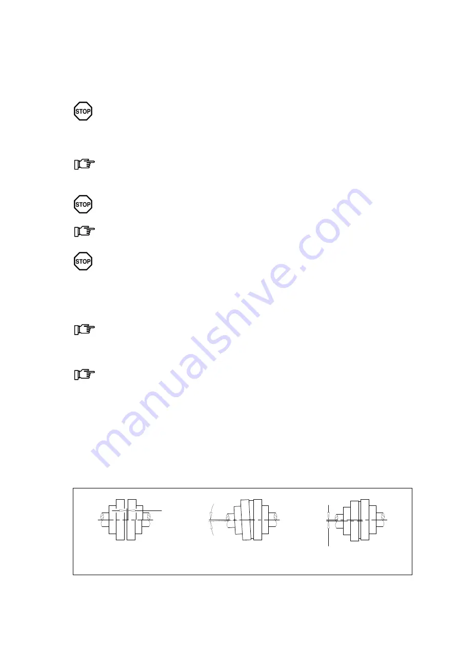
.The coupling parts may get out of alignment:
•
due to imprecise alignment during assembly or installation
•
during operation of the system due to:
─ heat expansion,
─ shaft flexure,
─ too weak machine frames, etc.
ΔKa
Axial misalignment
(ΔKa)
Angular misalignment
(ΔKw)
Radial misalignment
(ΔKr)
ΔKw
ΔKr
Fig. 17:
Possible misalignments


