
154 / 244
Siemens
Standard application AHU
CE1P3977en_02
Building Technologies
Configuration
01.02.2010
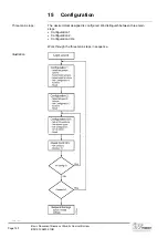
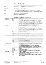
15.1 Configuration 1
Set superposed settings for the plant in Configuration 1.
– Configuration occurs setting-by-setting, i.e. you cannot bypass any lines.
– Configuration 1 must be completed with reset prior to starting Configuration 2.
As required: Enter password for level 4:
Start page > Password Enter
then:
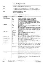
Main Index > Configuration > Configuration 1
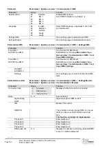
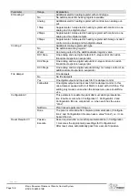
Parameter
Range
Explanation
General
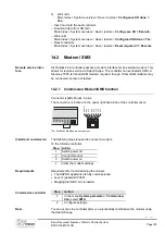
Extension modules
No
The basis controller I/Os are enough for configuration.
One
One extension module is connecting using address 1.
DIP switches 5 and 6 must be set to ON on the module.
Two
Two extension modules are connected with addresses 1 and 2.
DIP switch 5 must be set to ON on extension module 1; on exten-
sion module 2, DIP switches 4 and 6.
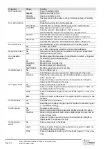
Fire alarm
No
No fire alarm.
alarm
External fire alarm such as smoke detectors, thermostats, fire de-
tection control units, etc.
tmp
Internal fire alarm via temperature measurement of supply and ex-
haust air temperature, when both sensors exist. A fire alarm is trig-
gered when on of the two temperatures breaches a certain value.
alarm+tmp
Both fire alarms.
Filter alarm
No
No filter alarm.
Combined
Supply and exhaust filter with common alarm input.
Supply
Supply filter alarm input only.
Exhaust
Exhaust filter alarm input only.
Sply+Exh
Two separate filter alarm inputs for supply and exhaust filters.
Emergency stop
No
Yes
Input for emergency stop. A TRUE signal at this input immediately
shuts down the plant. No alarm is triggered.
Alarm ackn input
No
Yes
Input to acknowledge/reset an alarm. Alarms still pending are ac-
knowledged; no longer pending alarms are reset.
Su/Wi input
No
Yes
Input for Summer/Winter changeover: A TRUE signal on this input
means Summer = Enabled.
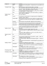
TSP function
No
No time switch program.
Steps
Time switch program with possible settings for fan stages (Off and
Stx). The parameter TSP Steps determines the number of possible
steps x.
Steps+tmp
Time switch program with settings for fan stages and temperature
control mode (Off, Ecox and Comx). The parameter TSP Steps
determines the number of possible stages x.
The temperature mode, comfort or economy have separate set-
points for temperature control.
TSP steps
Enable possible fan steps. This setting influences the number of
setpoints for controlled fans.
1Step
TSP function = Steps ---> Possible time switch program settings:
Off, St1.
TSP function = Steps+tmp ---> Possible time switch program set-
tings: Off, Eco1, Com1.
Task
Notes
Start
155 / 244
Siemens
Standard application AHU
CE1P3977en_02
Building Technologies
Configuration
01.02.2010
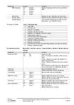
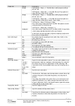
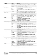
Parameter
Range
Explanation
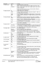
2Steps
TSP function = Steps ---> Possible time switch program settings:
Off, St1, St2.
TSP function = Steps+tmp ---> Possible time switch program set-
tings: Off, Eco1, Eco2, Com1, Com2.
3Steps
TSP function = Steps ---> Possible time switch program settings:
Off, St1, St2, St3.
TSP function = Steps+tmp ---> Possible time switch program set-
tings: Off, Eco1, Eco2, Eco3, Com1, Com2, Com3.
Example 1
Example 2
TSP function = Steps, TSP steps = 2Step.
Fan control using 2 setpoints for St1 and St2. Temperature control
using a setpoint for Comfort mode.
TSP function = Steps+tmp, TSP steps = 3
Fan control using 3 setpoints for St1 and St2 and St3. Temperature
control using separate setpoints for Eco and Comfort.
Under Eco2, the plant operates using the temperature setpoint for
Eco and the fan setpoint St2.
Ext control input
No
No external input for operating mode switch, timer, button, occu-
pancy detector, etc.
One
One input (e.g. off / on).
Two
Two inputs (e.g. Auto / Off / St1 / St2).
Alarm outputs
No
No alarm output.
One
One output (e.g. for high alarms).
Two
Two outputs (for high and low alarms).
External setpoint
No
No analog input for connect an external setpoint or an external
setpoint compensation.
Volt
Input for one 0-10V DC signal.
Ohm
Input for one 0-2500 Ohm signal.
QAA27
Input for QAA27.
BSG21
Input for BSG21 setpoint compensation.
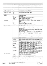
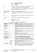
Sensors
Room tmp Sensor
No
1 sensor
2 sensor
1 RU
1snsr+1RU
2 RU
Inputs for room temperature sensor. You can select whether to ap-
ply maximum, minimum, average or individual value for control for
more than one sensor in Configuration 2. When selecting 1 RU,
1snsr+RU or 2 RU, the interface to the room unit connection is en-
abled.
Exhaust tmp sensor
No
Yes
Input for return air sensor.
Yes+Hold
The maximum, otherwise present temperature is stored when shut-
ting down the plant, to the extent the plant ran for more than 5
minutes.
The setting only makes sense when there is no room sensor and
night start operations (e.g. night cooling) without plant kick are to
be used. (Plant kick: Short, cyclical plant start to update the values
of the sensors mounted in the duct).
Supply tmp sensor
No
Yes
Input for supply air sensor.
Outs air tmp Sensor
No
Yes
Input for outside air temperature sensor.
Yes+Hold
The minimum, otherwise present temperature is stored when shut-
ting down the plant, to the extent the plant ran for more than 5
minutes.
Basis Document Siemens Climatix Control System
BDCX.100820.01GB
Page 154
Содержание Climatix Series
Страница 1: ...Control Equipment Siemens Climatix Basis Document Climatix Control System ...
Страница 2: ......


