7SG11 Argus 1 Diagrams and Parameters
©2010 Siemens Protection Devices Limited
P20008 Page 5 of 33
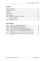
Contents
Software Release History ......................................................................................................................2
Hardware Release History .....................................................................................................................4
Contents ..................................................................................................................................................5
List of Figures.........................................................................................................................................5
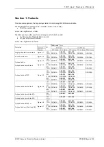
Section 1: Variants .................................................................................................................................6
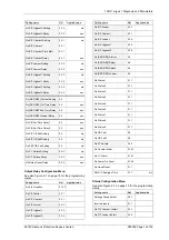
Section 2: Settings ...............................................................................................................................11
Section 4: Application Diagrams ........................................................................................................29
List of Figures
Figure 2-1
Status Input and Output Relay Programming Matrix .........................................................15
Figure 4-1
Typical Connection for Earth-fault Protection ....................................................................29
Figure 4-2
Typical Connection for Sensitive Earth-fault Protection ....................................................30
Figure 4-3
Typical Connection for 3 Phase-fault Protection ...............................................................30
Figure 4-4
Typical Connection for 2 Phase-fault and Earth-fault Protection.......................................31
Figure 4-5
Typical Connection for 2 Phase-fault and Sensitive Earth-fault Protection .......................31
Figure 4-6
Typical Connection for 3 Phase-fault and Earth-fault Protection.......................................32
Figure 4-7
Typical Connection for 2 Phase-fault, Earth-fault and Sensitive Earth-fault
Protection...........................................................................................................................32
Figure 4-8
Typical Connection for 3 Phase-fault and Sensitive Earth-fault Protection .......................33
Figure 4-9
Typical Connection for 3 Phase-fault and Earth-fault Protection – 1A or 5A
Version...............................................................................................................................33

