7SG11 Argus 1 Diagrams and Parameters
©2010 Siemens Protection Devices Limited
P20008 Page 15 of 33
51
P/F Charact.
time delayed overcurrent
50
P/F Lowset
instantaneous overcurrent
50
P/F Highset 1
instantaneous overcurrent
50
P/F Highset 2
instantaneous overcurrent
P/F Charact Inhib
P/F Lowset Inhib
P/F Highset 1 Inhib
P/F Starter
P/F Highset 2 Inhib
P/F Charact.
P/F Lowset
P/F Highset 1
P/F Highset 2
51N
E/F Charact.
time delayed overcurrent
50N
E/F Lowset
instantaneous overcurrent
50N
E/F Highset 1
instantaneous overcurrent
50N
E/F Highset 2
instantaneous overcurrent
E/F Charact Inhib
E/F Lowset Inhib
E/F Highset 1 Inhib
E/F Starter
E/F Highset 2 Inhib
E/F Charact.
E/F Lowset
E/F Highset 1
E/F Highset 2
SEF Delay 1 Inhib.
SEF Delay 2 Inhib.
SEF Lowset Inhib.
50N / 87G
SEF/REF
sensitive earth-fault
/ restricted earth-fault
SEF Starter
SEF Lowset
SEF Delay 1
SEF Delay 2
Drop-off Delay (ms)
Pick-up Delay (ms)
Inverted Inputs
Settings Group
Select
self supervision
Prot. Healthy
S1
S2
S3
S4
S5
S6
S7
S8
S9
74TC
Trip Circuit Fail
trip circuit supervision
Trip Circuit Fail
Relay Identifier
Relay Address
Settings Group
Argus Elements.vsd/AG1
R1
R2
R3
R4
R5
R6
R7
R8
R9
R10
R11
Alarm 1
Alarm 2
Alarm 3
Alarm 4
Alarm 5
Reset Flag & Outputs
output relay control
Hand Reset
Min O/P Energise Time
R1
R2
R3
R4
R5
R6
R7
R8
R9
R1
0
R1
1
50BF
CB Fail
circuit breaker failure
Fault Trigger
CB Fail 1/ CB Fail 2
CT Failure Alarm
circuit breaker operation counter
Counter Alarm
Σ
I
2
Alarm
waveform recorder
Waveform Trig
Σ
I
2
Update
Counter Reset
real time clock
Clock Sync
fault recorder
Fault Trigger
Status 1
Status 2
Status 3
Status 4
Status 5
Status 6
Status 7
Status 8
Status 9
CT Failure
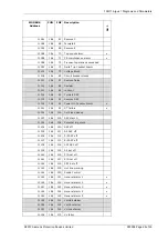
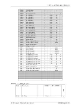
Figure 2-1
Status Input and Output Relay Programming Matrix

