7SG11 Argus 6 Diagrams and Parameters
©2013 Siemens Protection Devices Limited
P20011 Page 15 of 22
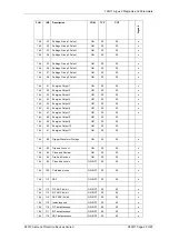
Table Showing Command Information (INF) Numbers
FUN
INF Description
GI
TYP
COT
DIR
A
rg
u
s
6
160
2 Reset FCB
-
5
3
RO
x
160
3 Reset CU
-
5
4
RO
x
160
4 Start/Restart
-
5
5
RO
x
160
5 Power On
-
5
6
RO
x
160
16 ARC in progress
x
1
1, 9, 12, 20, 21
RC
x
160
19 LEDs reset
-
1
1, 7, 11, 12, 20, 21
RO
x
160
21 Trip Test
x
1
1, 9
RC
x
160
22 Settings changed
x
1
1, 9, 11, 12
RC
x
160
23 Setting G1 selected
x
1
1, 9, 11, 12, 20, 21
RC
x
160
24 Setting G2 selected
x
1
1, 9, 11, 12, 20, 21
RC
x
160
25 Setting G3 selected
x
1
1, 9, 11, 12, 20, 21
RC
x
160
26 Setting G4 selected
x
1
1, 9, 11, 12, 20, 21
RC
x
160
27 Input 1
x
1
1, 9
RC
x
160
28 Input 2
x
1
1, 9
RC
x
160
29 Input 3
x
1
1, 9
RC
x
160
30 Input 4
x
1
1, 9
RC
x
160
36 Trip circuit fail
x
1
1, 9
RC
x
160
46 Group Warning
x
1
1, 9
RC
x
160
47 Alarm
x
1
1, 9
RO
x
160
64 A-starter
x
2
1, 9
RC
x
160
65 B-starter
x
2
1, 9
RC
x
160
66 C-starter
x
2
1, 9
RC
x
160
67 E-starter
x
2
1, 9
RC
x
160
68 General trip
-
2
1
RO
x
160
69 A-general trip
-
2
1
RO
x
160
70 B-general trip
-
2
1
RO
x
160
71 C-general trip
-
2
1
RO
x
160
84 General starter
x
2
1, 9
RC
x
160
85 Circuit breaker fail 1
-
2
1
RO
x
160
91 P/F-general HS trip
-
2
1
RO
x
160
92 E/F-general trip
-
2
1
RO
x

