7SG11 Argus Technical Reference
©2013 Siemens Protection Devices Limited
P20007 Page 36 of 71
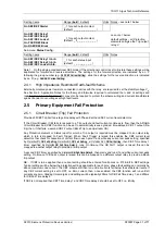
Setting name
Range (
bold
= default)
Units Notes
2-Out-Of-3 Gate Logic
OFF
, ON
+30,
+45
Type I element.
P/F Charact Angle
-90, -89…
+45
…+90
Type II element.
0,
-15
, -45, -65
Type I element.
E/F Charact Angle
-90, -89…
-15
…+90
Type II element.
SEF Charact Angle
0,
-15
, -45, -65
Type 1 only
Voltage Memory
OFF, 0.1 … 0.5
sec
Sub-menu:
O/P Relay Config.
Setting name
Range (
bold
= default)
Units Notes
Gn P/F FWD Block
Gn P/F REV Block
Gn E/F FWD Block
Gn E/F REV Block
_, 1 for each output contact
(default:
_ _ _ _ _ _ _ _ _ _ _
)
Gn SEF FWD Block
Gn SEF REV Block
_, 1 for each output contact
(default:
_ _ _ _ _ _ _ _ _ _ _
)
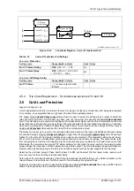
Argus 2 single-pole directional
SEF only.
2.8 Voltage Protection
Argus 2 (type II) models only
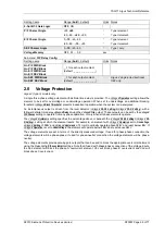
A single three-phase voltage element with definite time delay is provided. The
Voltage:
V Operation
setting allows the
element to be set for overvoltage or undervoltage operation. When set to undervoltage an additional blocking
threshold (
Voltage:
V Block Threshold
) prevents inadvertent operation when the system is de-energised.
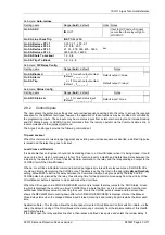
An instantaneous output is driven from the level detector (
Voltage:
V Ph-Ph Setting
)/(
Voltage:
V Ph-N Setting
), with a
follower definite time delay
Voltage:
V Delay
driving the
Voltage:
V Trip
output. These outputs can be set by the
Voltage:
V
O/P Phases
setting to operate from any phase operation, or only when all phase elements operate.
The
Voltage:
V Hysteresis
setting specifies the percentage above or beneath the (
Voltage:
V Ph-Ph Setting
)/(
Voltage:
V Ph-
N Setting
), setting at which the element resets. For example, an element with
Voltage:
V Operation
set to
Overvoltage
,
Voltage:
V Setting
of
100 V
and
Voltage:
V Hysteresis
of
1 %
will nominally operate above
100 V
and reset below
99 V
. If
Voltage:
V Operation
is set to
Undervoltage
, the element will operate below
100 V
and reset above
101 V
.
The voltage elements are set in terms of the directly measured voltage. If used for phase-phase connection the
voltage elements will be phase-phase; if used for phase-neutral connection the voltage elements will be phase-
neutral.
The voltage elements provide pole-by-pole outputs that can be used to block the appropriate overcurrent element
using the
Status Config.:
P/F xxxx Inhibit
settings. Note that if used with phase-phase connection of the voltage inputs,
the Vab element will block the phase A overcurrent element, Vbc will block phase B overcurrent and Vca will
block phase C overcurrent.


