COMMISSIONING
6
57
8021804/2017-11-27|SICK
Subject to change without notice
T R A N S L A T I O N O F T H E O R I G I N A L I N S T R U C T I O N S | Telematic Data Collector
5. For SICK sensors, it is necessary to enter the TDC device interface being used for the
voltage supply to the sensor in the
Power Supply
field (for further information on this,
refer also to Chapter
5.1.4 Connecting the TDC device to SICK sensors
A list of all the possible voltage supply interfaces will be displayed for the type of device
selected.
Select the proper interface.
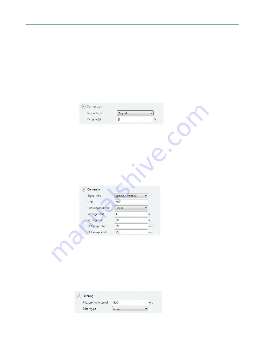
Conversion
1. When a SICK sensor is selected, the corresponding signal type will be automatically
entered in the
Signal kind
field. This is
Digital
in the example shown.
The signal type entered can be updated accordingly for sensors that can emit both
analog and digital signals.
2. The value displayed in the
Threshold
field indicates the value used as the threshold
for processing a digital signal. In the example shown, this value is 5 V. If the value
falls below the threshold, the input value is taken and displayed as an output value of
0
(status:
Low
) and if the value exceeds the threshold, the input value is taken and
displayed as a constant output value of
1
(status:
High
).
The relevant input fields will be displayed when analog signals are being processed.
Filtering
The filter settings will have been preset once a SICK sensor has been selected. These
settings can normally be adopted as they are.
The value in the
Measuring interval
field indicates the intervals at which signal values
should be transferred from the interface to the TDC device. The default setting is 500 ms,
in which case two signal values will be processed from the connected sensor within
1 second.
Note


