


9
SICK LSI Technical Description - 06/98
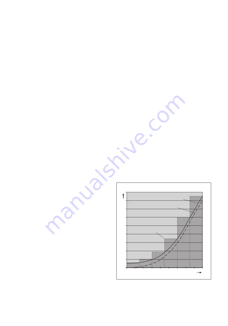
Speed
Safety supplement
Vehicle braking distance
Protective field depth
Distance
The braking distance of the vehicle plus the safety supplement
produces the required protective field depth
5.2 Mobile protection: For on-board
vehicle use
With the aid of incremental sensors, you can adapt the size of
the monitored area to the speed of the vehicle.
Note:
The two incremental encoders must be mounted such that one
continues to work safely and fault-free in the event of failure of
the other. In this, failure of the incremental encoders must be
prevented by design, mechanical and electrical means.
Also make sure that the systematic influences (such as
temperature, shaft breakage, slip) are not able to influence the
speed recording of both incremental encoders at the same time.
The incremental encoders must meet the following
requirements:
Type: two-channel rotary encoder with 90° phase offset
Supply voltage: 24 V DC
Outputs: push/pull
Protection IP54 or higher
Shielded cable
Max. pulse frequency: 100 kHz
Determine the number of pulses each incremental encoder
delivers per centimetre covered by your vehicle, running in a
straight line. You will need these figures to configure using the
PLS/LSI user software (see section 9.7 and the calculation
example in the appendix, section 11.1).
Calculating the protective field depth on the vehicle:
When calculating the required protective field depth on a vehicle
you must take into account that the braking distance increase is
not linear, but quadratic, as the speed increases (see diagram).
Note:
For precise information on the required protective field depth
and on the necessary safety supplements refer to the technical
description of the PLS.
•
Define the required speed range for your application.
•
Calculate the longest braking distance for each speed range
(i.e. the braking distance for the upper speed limit).
•
Add to that distance the necessary safety supplements (see
technical description of PLS).
This will give you the required protective field depth for each
speed range.
•
Configure the protective fields using the PLS/LSI user
software, as described in section 9.7.
Содержание LSI 101
Страница 1: ...T E C H N I C A L D E S C R I P T I O N L a s e r S c a n n e r I n t e r f a c e L S I 1 0 1...
Страница 2: ...Certification 2 8 008 310 Technical Description SICK AG Safety Systems Germany All rights reserved...
Страница 4: ...4 SICK LSI Technical Description 06 98 1 Approvals and Certificates...


