
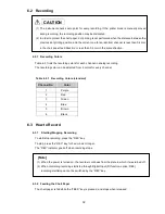


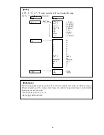


45
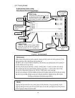
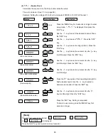
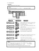
7.1.1 Setting the Range
(1) Setting method
With a multirange system, setting the range for each channel is possible.
Use the
key to shift the mode
1
to
10
shown in the Table below.
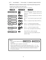
Set the range from the following input signals. (Modes
1
to
3
)
DC voltage:
10 mV DC, 0 to 20 mV DC, 0 to 50 mV DC,
200 mV DC,
1 V DC, 0 to 5 V DC,
10 V DC
Direct current: 4 to 20 mA DC (External shunt resistor: 250
)
Thermocouple: B, R, S, K, E, J, T, C, Au-Fe, N, PR10-20, PL- , U, L
RTD:
Pt100, JPt100
For the thermocouple and RTD, an optimum range is automatically selected depending on
the set span point.
Sets scaling, square root, decade, interchannel sum/difference/average. (Modes
4
to
9
)
Unnecessary channels can be skipped. (Mode
10
)
Setting
Channel
Mode
Key
1
(Voltage, Current)
2
(Thermocouple)
3
(Resistance temperature detector)
4
(Scaling)
5
(Square root)
6
(Decade)
7
(Difference)
8
(Sum)
9
(Average)
10
(Skip)
key
Can be set for
all channels.
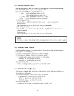
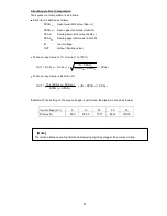
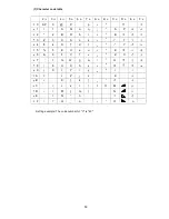
[Note]
A decimal point arbitrary position can be set only in "scaling" and "square root" modes. When altering
the decimal point position in Voltage/Current/Thermocouple/RTD input, set it in the "scaling" mode.
To fix the decimal point position, set it as follows.
Input
Digits after decimal point
Input
Digits after decimal point
mV
1, 0 to 5 V
10 V
mA
2 digits
3 digits
2 digits
2 digits
.00
.000
.00
.00
Thermocouple
RTD
200 mV DC
1 digit
1 digit
1 digit
.0
.0
.0


