background image

SJGF60XT

48

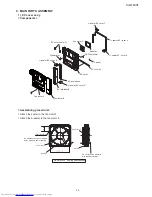
Ice maker ass’y T-SK

6) 
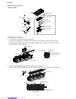
<Components>

Plate

Ice cube maker

Ice cube tray AT

Thermistor

Thermistor cover

Sealer

Ice cube heater

Ice heater cover T

I-grill

Harness cover

Ice maker ass’y

Ice senser

L-band C

<Assembling procedure>

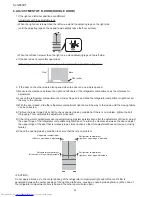
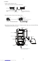
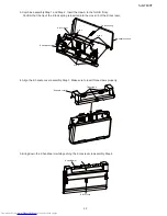
Put Thermistor on back side of Ice cube tray AT. 


1. 

Pu

• 

t Selar on Thermistor, cover them with Thermistor cover and fix by 4 claws and square holes.

Place the Sealer on the Thermistor, and put the Thermistor cover over it and fix it with four claws

• 

(square holes, round protrusions).   

Ice cube tray AT

Ice cube tray AT

Thermistor

Thermistor

Thermistor cover

rib

rib

Set the rib between
the 2 lead wires.

Sealer

claw

square hole


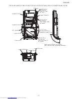
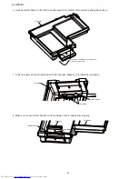
Insert the ice cube heater along the groove of the ice cube tray AT.

2. 

Attach it without twisting the heater so that the mark can be seen around the entire circumference.

• 

Ice cube tray AT

The marking existence side

Put it well.

Align the end face of 
the protective tube with the rib. 

Align the end face of 
the mold with the rib. 

Attach the end face of 
the protective tube to the boss.

How to install the ice cube maker

(Figure of back side)

Mark of Ice cube heater

1.5

0.2

Loosen.

Ice cube heater

Содержание SJ-GF60X-T

Страница 1: ...CAUTIONS FOR USING LEAD FREE SOLDER 12 5 ELECTRICAL SYSTEM SPECIFICATIONS 13 1 FUNCTIONAL PART SPECIFICATIONS 13 2 MODE FOR DISPLAY 14 6 REFRIGERATION CYCLE SYSTEM SPECIFICATIONS 1 R600A PRECAUTIONS 15 2 TABLE OF R600A CHARACTERISTICS 15 3 REFRIGERATION CYCLE DIAGRAM 15 4 REPAIR OF THE REFRIGERATION CYCLE 17 7 TROUBLESHOOTING 1 SELF DIAGNOSIS MODE 18 2 FORCED STOPPING OF DOOR ALARM BUZZER 22 3 THE...

Страница 2: ...Cabinet Inner box material ABS plastic Outer shell material PET steel Hot dipped zinc plated steel sheet with baked polyester resin coating Door Door shell material Glass Door inner material ABS plastic Temperature control Automatic adjustable Defrosting system Heater system automatic start automatic finish Refrigerator lamp LED 8 pcs Adjustable legs 2 Casters 4 Climate class ST PLUG TYPE Plug cor...

Страница 3: ...e making capacity External air temperature 30ºC No door opening closing Temperature control 中 Ice making mode 通常 Ice cube size Standard Large Daily Approx 1 2 kg Approx 1 5 kg Once 8 pieces Approx 100 g Approx 230 g Ice making time once Ice cube size Standard Large Ice making mode 通常 Approx 2 hours Approx 3 hours and 30 minutes キラッ ト Approx 6 hours Approx 8 hours おいそぎ Approx 1 hour and 20 minutes ...

Страница 4: ...mpartment lower Noise proof sheet Ice storage box Ice scoop F case sus F case s F top case F bottom case Vegetable case Fruit case V case sus Pet case Vegetable compartment Vegetable compartment Free set shelf left Egg case Egg tray Water tank Bottle pocket left Bottle pocket right Cool plate Door pocket left Door pocket right Case Chilled case C case tray LED Free set shelf right Plasmacluster un...

Страница 5: ...per ass y V heater Thermistor Ice cube heater Evaporator Terminal box Main PWB EECON INV PWB REACTANCE Compressor protector valve turret Fan motor g Condenser unit Caster Evaporating pan Side view Adjustable leg ass y F proximity switch Ice maker ass y OP PWB Transparant electrode R door switch LED PWB ass y Cool plate LED PWB ass y R thermistor Gear pump Water pipe ass y Water pipe heater Tank he...

Страница 6: ...pper Freezer compartment lower Refrigerator compartment Freezer compartment lower Vegetable compartment Side view Front view Refrigerator compartment Ice compartment Freezer compartment upper Vegetable compartment Flow of Cool air When Plasmacluster ion is in operation ...

Страница 7: ...cations under the condition of no food inside doors closed and surrounding temperature is 30 after stabilized the inside temperature Temperature adjustment is 中 Approx 3 7 C Approx 2 5 C Approx 3 7 C Approx 0 2 C Approx 17 19 C Approx 18 20 C Approx 18 20 C Approx 3 8 C ...

Страница 8: ...IT mm 1 174 230 728 285 461 616 697 5 691 5 641 68 691 5 4 750 1820 853 2 180 8 335 365 8 8 15 5 50 732 5 125 118 Moving wheels back side Moving wheels front side Adjustable feet More than 960 1136 728 60 60 More than More than 60 More than 60 More than 90 mm ...

Страница 9: ... 619 353 357 215 208 208 584 593 366 208 172 118 6 7 9 5 9 6 9 6 246 226 392 81 5 70 70 417 8 424 420 280 50 112 203 412 589 589 135 334 334 309 334 142 142 144 75 75 75 144 75 122 123 123 123 135 94 163 417 8 1 0 5 6 6 1 0 0 7 1 348 3 1 1 9 1 1 319 348 50 424 597 282 310 63 353 88 105 404 110 5 138 5 95 5 89 440 119 113 125 140 ...

Страница 10: ...WB left Indicator PWB Plasmacluster unit Motor D fan motor PCI Gear pump Damper R thermistor F thermistor DEF thermistor Ice maker unit Motor Switch Thermistor Proximity switch F proximity switch Ice cube heater Water pipe heater R door heater V heater Door switch left Door switch right LED PWB right Terminal box Valve turret Humidity sensor Heater Thermo fuse Tank heater ...

Страница 11: ...mistor R door switch left R door switch right Water pipe heater SW Motor LED PWB right Ice cube heater Gear pump R damper Water pipe heater Source cord Black White White White Yellow Brown V heater harness Valve turret Valve turret Green Yellow Green Yellow Protector Black Yellow Proximity switch Moter Tank heater Proximity switch Black Brown Blue Black Red Gray Red Red Blue Orange Light green Yel...
Страница 12: ...ed and that the iron temperature is adjusted accordingly 3 Soldering As the melting point of lead free solder Sn Ag Cu is higher and has poorer wettability flow to prevent damage to the land of the PWB extreme care should be taken not to leave the bit in contact with the PWB for an extended period of time Remove the bit as soon as a good flow is achieved The high content of tin in lead free solder...

Страница 13: ...ure 120 C For compressor overload prevention Main PWB For main control OP PWB For operation panel control touch panel LED PWB 15V 72mA 1 125W For refrigerator compartment illumination Indicator PWB 3 2V 20mA 64mW Source cord 125V 7A Source cord 2 Pin earth F thermistor Resistance 6 4kΩ at 0 C For detection of the freezer compartment temperature R thermistor Resistance 6 4kΩ at 0 C For detection of...

Страница 14: ...display mode will be maintained not be cancelled Operation in the display mode 2 3 Each load compressor each fan motor all heaters damper ice release motor water pump motor stops 1 The damper is normally kept opened 2 Even if the ice compartment or the refrigerator compartment lower door is opened the door open buzzer does 3 not sound When the refrigerator compartment door is opened 4 The refriger...

Страница 15: ... 60 1 34 0 91 1 11 1 91 2 25 2 64 3 08 3 58 4 13 4 74 5 42 7 00 6 17 Unit Temperature C Pressure MPa abs Temperature Pressure 20 15 10 5 0 10 15 20 25 30 35 40 45 50 5 0 073 0 157 0 131 0 089 0 109 0 187 0 221 0 259 0 302 0 351 0 405 0 465 0 532 0 686 0 605 REFRIGERATION CYCLE DIAGRAM 3 Piping Diagram 3 1 Evaporator Charge pipe Compressor Discharge pipe kit Capillary tube B Dryer Capillary tube A ...

Страница 16: ...ra cond unit kit Extra cond unit D P condenser Capillary tube B I D 0 7 Piping detail drawing 3 3 Side condenser R Outlet Dew proofing condenser Inlet Side condenser R Inlet Suction pipe Charge pipe Discharge pipe ass y Evaporating pan Suction connector Suction connector ass y Side condenser L Outlet Compressor Charge pipe R valve ass y Dryer Side condenser L Inlet Extra cond unit ass y Pinch poin...

Страница 17: ... The fine capillary is identified with a yellow mark Fault and status of refrigerant valve 2 There is no method to give an instruction from the PWB and confirm the valve position Refrigerant valve status Problem 1 Both capillaries are opened and the valve does not operate No problem on cooling operation No problem 2 Only the fine capillary is opened and the valve does not operate Cooling performan...

Страница 18: ...ce Up to 9 items per day Note 1 Self diagnosis result data for 5 days including today are stored 24 hours from the time when the refrigerator power supply turned ON is defined as one day 24 hours 24 hours 24 hours 24 hours 24 hours 24 hours Today Current time 1 day before 2 days before Stored data 3 days before 4 days before n days before Refrigerator power supply is turned ON Note 2 How to clear ...

Страница 19: ...damper is forcedly opened Opening closing the refrigerator compartment door activates the R damper operation During execution of the self diagnosis mode and for 20 minutes after cancellation of this mode self diagnosis data serial output is executed During execution of the self diagnosis mode and for 20 minutes after cancellation of this mode the door open buzzer does not sound Operation during se...

Страница 20: ...t Display of the fault just before the last 3 days before fault history 4 days before fault history During forward reverse scroll of fault display with button if fault data to be displayed next does not exist the buzzer sounds beep beep and the display will not change To display a fault occurrence date for currently displayed data press the 冷凍 温度 lamp Fault occurrence date 冷凍 温度 lamp Current Unlit...

Страница 21: ...r supply clock fault Ice cube maker thermistor high temperature F thermistor high temperature R thermistor high temperature R thermistor low temperature External air temperature information Door open information Inverter wiring error Inverter overload protection Inverter startup fault Inverter overcurrent Inverter PWB communication error Inverter position detection fault PCI fault Wiring disconnec...

Страница 22: ...connect connectors and measure the pins on the wiring side Ω 2 Without disconnecting connectors measure the voltage of the connector pins V Note Use a tester with a large internal impedance Microcomputer Connector IC1 A D On the circuit board 5V 1 Thermistor 2 Table of Thermistor Characteristics 1 3 1 30 0 25 0 20 0 15 0 10 0 5 0 0 0 5 0 10 0 15 0 20 0 25 0 30 0 35 8 26 1 19 3 14 4 10 9 8 3 6 4 5 ...

Страница 23: ...ng cycle 4 Replace the inverter PWB or main PWB Cooling performance is in sufficient The compressor is working DEF thermistor fault External air temperature thermistor fault 1 Connector insertion check Main PWB intermediate connector 2 Thermistor resistance check Check the value in the thermistor characteristic table 3 If the above check results are normal 1 Correct the installation 2 Replace the ...

Страница 24: ... main PWB Ice making failure Ice making speed is low Ice release operation error 1 Connector insertion check Main PWB intermediate connector 2 Ice maker ass y installation condition operation check 3 If the above check results are normal 1 Correct the installation 2 Correct the installation or replace the ice maker ass y 3 Replace the main PWB Ice maker thermistor fault 1 Connector insertion check...

Страница 25: ...ity or is indicated the judgment result is acceptable 4 This procedure is intended for simplified check of fan motor and plasmacluster operations Even if the ion quantity specified in the catalog cannot be confirmed it is no problem Reason why the ion quantity specified in the catalog cannot be confirmed Because the ion quantity specified in the catalog has been measured in stable operating condit...

Страница 26: ...ment Accessories Shelves Chilled case Water tank Partition support C shelf ass y Duct RT ass y R shower duct ass y PCI box ass y R C box ass y Connector cover R Pipe cover 2 Freezer compartment Accessories Ice storage box Freezer cases SW cover Ice maker ass y T SK C part FI B C part FI FK When replacing Proximity switch E V cover ass y Heater DEF thermistor holder When replacing F proximity switc...

Страница 27: ...lathead screwdriver and push the entire part toward the direction of arrow while twisting it to take it off Freeset stay How to remove C case cover 2 C shelf ass y back side C case cover C shelf ass y with the C case cover attached Unhook three claws at the back and pull out the protrusions in front Claws at the back Protrusion C case cover Installation is the reverse procedure to removal How to r...

Страница 28: ...se the claws at the front at 2 places The claws are directly applied to the food liner Use caution not to damage the food liner After the claws are released pull the box downward and release the remaining claws Disconnect two connectors claw screw D PCI box ass y Remove the connector cover R Screw at 1 place 7 Claws at 2 places and disconnect four connectors Connector cover R claw screw Remove the...

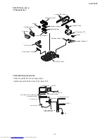
Страница 29: ... When replacement of F LED PWB ass y SW cover Remove the Ice maker ass y T SK 2 Remove the screw and pull it toward you while 1 pressing the claw on the front Remove connector 2 Ice maker ass y T SK claw Screw Remove the damper 10 Damper CAUTION Precautions for handling the ice maker ass y T SK Securely insert the 4 claws If the claws are not inserted completely and they come loose the ice maker a...

Страница 30: ...the Heater at the specified positions Make sure that they will not touch the metal edges of the cooling unit heater cover etc Be sure not to damage the piping of the cooling unit When connecting the connector check for a connector insertion fault After replacement of the heater check continuity and insulation When handling the heater hold the rubber cap Do not touch the glass pipe with a bare hand...

Страница 31: ...ount the evaporator in the original condition 7 CAUTION Put the bottom of the evaporator on the rib of the drip tray and place the projection of the food liner at the position shown in the figure Set the accumulator piping angle as shown in the figure Make sure that the pipe is not remarkably deformed Accumulator Fastening part HOW TO REMOVE OP PWB ASS Y 4 Insert a thin flathead screwdriver or a s...

Страница 32: ...nlarged view Bottom enlarged view Hole R sub packing sealer R sub packing sealer R door L ass y Fasten the R sub packing with the claws of the R door ass y front 8 places back 6 places First claw either 2 top or bottom of the packing to fasten it and then claw the remaining points in sequence The figure below shows R door L ass y Claw Make sure that a certain clearance is provided so that the R su...

Страница 33: ...e a gap Inside Duct RT rivet Duct RT ass y With a Duct RT rivet inserted the claw of the Duct RT ass y cover is spread apart and held in place in the holder at the ceiling Duct RT rivet Structural view of Duct RT rivet section Duct RT rivet After inserting the Duct RT rivets confirm that the head of the Duct RT rivet and the edge outside of the depression of the cover are at the same height How to...

Страница 34: ...ntil the closing failure 3 can be corrected Tighten the lower hinge bolt by half to check opening closing conditions If there is no problem tighten the bolt 4 thoroughly This completes the adjustment procedure If the refrigerator compartment door opening closing problem persists even after the adjustment of Step 4 adjust 5 the upper hinge of the refrigerator compartment right left door To widen th...

Страница 35: ...n A A sealer EV cover D EV insulation B Fan louver B EV cover sealer N A sealer EV cover B F thermistor Assembling procedure Attach the sealer to the fan motor F 1 Attach the A sealer to the fan motor F 10 40 Fan motor F A sealer A sealer Fan motor F Fan motor F Start of sealing No clearance or no overlapping at the start and end of sealing Do not pinch the lead wire with the seal material Sealing...

Страница 36: ...ape Paper tape Overlapped Overlapped Apply tape along the edge Apply tape so that there is no clearance between EV insulation A and B Start of sealing Start of sealing Apply tape along the edge Overlapped Overlapped Start of sealing Mounting the F thermistor fan motor F and EV insulation ass y 3 Fit the EV insulation ass y in the EV cover Wind the EV cover sealer N on the F thermistor Mount the F ...

Страница 37: ...r E A sealer EV cover E EV cover EV cover AL A sealer EV cover A Fan louver A EV cover L band C EV cover sealer N DEF thermistor Fan motor F Fan louver A Fan louver B Overlapped Fan louver on the back face Overlapped Apply the sealer to both fan louver A and EV cover Wind the sealer on the lead wire and fit it in the groove Cut out a surplus part Start of sealing Overlapped Viewed in direction of ...

Страница 38: ...ttach the A sealer R S duct B to the R shower duct cover T 1 Attach A sealer R S ducts C to the R shower duct insu 2 R shower duct insu R shower duct insu sealing specifications A sealer R S duct B A sealer R S duct B A sealer R S duct C Put the A sealer R S duct B on so that it comes to the top R shower duct cover T R shower duct insu A sealer R S duct C A Arrow view A A A R shower duct cover T A...

Страница 39: ...aw to the insulation securely 5 Insert the catalyzer 6 R shower duct cover R shower duct cover B Catalyzer Apply the hook to the R shower duct insu Insert the catalyzer with the claws spread out R shower duct insu Claw Center cover L Center cover R Cool plate R shower duct insu Apply the hook to the R shower duct insu Apply the hook to the R shower duct insu Apply the hook to the R shower duct ins...

Страница 40: ...ar pump R C box R thermistor R C box insu B R C box insu A Assembling procedure Insert the joint packing in the gear pump 1 Mount the joint packing vertically Joint packing Gear pump Mount the assembly of Step 1 to the R C box 2 Make sure that the joint packing is securely fit in the support part Gear pump Joint packing R C box Support part ...

Страница 41: ...crew Screw Packing holder Hinge Engage the hook Groove of R C box Attach the harness to the hook Insert the joint pipe to the gear pump 4 Insert securely Attach the joint pipe vertically as shown the figure Mount the R thermistor to the R C box 5 Gear pump R thermistor Attach the harness to the hook Paper tape Attach the joint pipe vertically Joint pipe Attach A sealer R FM S to the fan motor and ...

Страница 42: ...5 20 A sealer RCbox A R C box insu A A sealer RCbox A R C box insu A A sealer RCbox A R C box insu A A sealer RCbox B R C box insu B A sealer RCbox B R C box insu A A sealer RCbox A A sealer RCbox B A sealer RCbox B R C box insu B R C box insu A A sealer RCbox A A sealer RCbox B Start of sealing Start of sealing Overlapped End of sealing Start of sealing Sealing reference position Start of sealing...

Страница 43: ...Put the A sealer on the C insu FI 1 Put it on so that there is no space between the sealer and the insulation Start of sealing Start of sealing A sealer FI A sealer FI A sealer FI C insu FI C insu FI Lap over 20 60 Attach the proximity switch to the C insu FI FL 2 Paper tape 20 15 Hook the claw Twist the harness twice around the boss Proximity switch C part FI FL ...

Страница 44: ...assembly Step 3 and screw it on 4 Put the A sealer FIA B and C A sealer FIA A sealer FIA A sealer FIC A sealer FIB A sealer FIB A sealer FIB Sealing standard Sealing standard Sealing standard Hook the claw Hook the claw Hook the claw Hook the claw C part FI FR C part FI FR C part FI FR C part FI FL C part FI FL C part FI FL ...

Страница 45: ...er D PCI box ass y Absorbent rubber B Absorbent rubber A Motor Assembling procedure Attach A sealer PCI fan and paper tape 1 Attach A sealer PCI fan to the D fan motor PCI 3 10mm A sealer PCI fan A sealer PCI fan D fan motor PCI D fan motor PCI Doubled No protrusion from discharge port as reference position Sealing start position Paper tape To plasmacluster unit To indicator PWB ass y After Clawin...

Страница 46: ... holder Motor Screw Check the looseness of the screw Screw Check the looseness of the screw Fit the projection of the D damper flap in the hole of the D damper holder Fit the projection of the motor in the hole of the D damper flap and fasten it with the screw Mount the assembly of Step 1 D PCI cover O catalyzer absorbent rubbers A and B Indicator PWB and 4 Plasmacluster unit to the D PCI box ass ...

Страница 47: ...box A A sealer PCI fan A sealer D PCI box A Put it on so that the A sealer D PCI box A overlaps the A sealer PCI fan Hook the claw on the D PCI box to the D PCI cover at 1 place D PCI box ass y D PCI cover Attach A sealer D PCI box in the range of A Do not deform the sealer by stretching it excessively Hook the claw on the D PCI box to the D damper holder at 2 places Hook the claw on the D PCI box...

Страница 48: ...r claws square holes round protrusions Ice cube tray AT Ice cube tray AT Thermistor Thermistor Thermistor cover rib rib Set the rib between the 2 lead wires Sealer claw square hole Insert the ice cube heater along the groove of the ice cube tray AT 2 Attach it without twisting the heater so that the mark can be seen around the entire circumference Ice cube tray AT The marking existence side Put it...

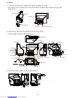
Страница 49: ...Ice senser points final gear of Ice maker ass y Use jig to prevent variability fixing Ice senser Tightning torque is 0 5N m Screw Ice maker ass y Ice maker ass y Final gear Move this direction remove backlash Groove Rib Head Ice senser Insert the assembly of Step 3 to the assembly of Step 4 5 Make sure that the ice cube tray AT is attached in the right direction The ice making section comes to the...

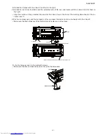
Страница 50: ...ss of the ice maker ass y so that it can be inserted into the hole of the I grill After it is inserted make sure to confirm that the stopper is securely in place Confirm that the tip of the ice sensor is in the release hole Make sure that there is at least 2 5mm space between the tip of the ice sensor and the release hole harness of Ice maker ass y Legs of Ice maker ass y axis of Ice cube tray AT ...

Страница 51: ... marking black band of the ice heater cover T 2 Fix the ice maker ass y and the harnesses of the ice maker thermistor and ice cube heater with the L band C Make sure that the harnesses of the thermistor and heater are not too loose L band C Make sure that protective tube is covered by the heater cover L band C I grill 55 5 Marking of the ice heater 2 1 Fix the harness cover to the I grill with scr...
Страница 52: ...r K handle cover label K handle support K lock rever K lock spring K handle Lock unit Assembling procedure Install the K handle arm and K lock rever to the K handle base 1 K handle base K lock rever K handle arm Install the K lock spring to the K handle support 2 K lock spring K handle support ...

Страница 53: ...rted into the cross rib of the K lock lever K lock spring Claw A Claw A Form B K handle base K lock rever K handle support Align the K handle cover assembly Step 3 Make sure to insert three claws properly 4 K handle cover Three claws Bring down the K handle arm while pushing the K lock lever in assembly Step 4 5 K lock rever K handle arm ...

Страница 54: ... Put the dent of K handle base from the bottom to the convex of fruit case Hook two claws on the K handle base to the fruit case Make sure to insert them properly 7 Fruit case K handle base Two claws Make sure to insert the K handle into three claws on the K handle arm properly 8 K handle Three claws K handle arm Fruit case ...

Страница 55: ...harness 2 Pull the harness tube of the fan motor G to the connector side and attach the W sealer G fan harness to the tube 15 15 30 30 30 30 40 15 15 30 30 30 15 15 15 15 30 220 5 W sealer g fan W sealer g fan W sealer g fan W sealer g fan Fan motor G W sealer g fan hnss W sealer g fan harness With the harness pulled to the connector side attach the W sealer G fan harness Attach the W sealer G fan...

Страница 56: ...r after sales service only The contents are subject to change without notice SJGF60XT Refrigerator freezer MODEL SJ GF60X T PartsGuide 1 SJ GF60X T DOOR 2 SJ GF60X T CABINET1 3 SJ GF60X T CABINET2 4 SJ GF60X T CABINET3 5 SJ GF60X T CYCLE 6 SJ GF60X T OTHER PARTS INDEX ...

Страница 57: ...35 5 36 3 19 3 24 3 1 5 14 3 4 3 20 3 25 3 21 5 9 5 42 5 21 5 41 5 10 5 18 5 13 5 37 3 3 5 19 3 7 3 7 3 22 3 6 3 10 3 10 3 5 2 3 5 1 3 23 3 9 3 8 3 5 1 3 5 3 3 5 3 5 2 5 15 3 32 3 32 3 31 3 33 3 30 5 21 5 5 21 3 5 21 1 5 21 2 5 16 1 5 16 2 5 21 4 5 21 6 5 21 7 5 20 5 33 5 26 1 3 3 40 3 39 3 8 3 5 3 1 3 2 3 2 3 35 3 37 3 13 3 11 2 3 11 3 3 11 3 11 1 5 21 11 5 11 ...

Страница 58: ...r f door liner 3 33 PSEL E855CBZZ AD A sealer 3 35 PSEL E739CBZZ AD A sealer r door r b 3 37 PSEL E361CBZZ AD A sealer r door l b 3 39 PSEL E582CBZZ AB Sub packing sealer 3 40 PSEL E753CBZZ AB Sub packing sealer T 5 1 DTNA A230CBKZ AR Free set shelf ass y 5 2 FTNA A650CBKZ AP Free set shelf ass y 5 3 DTNA A235CBKZ AY R shelf ass y 5 5 UTNAPA050CBFA AE Egg tray 10a 5 6 UYOK A667CBFB AM Egg case 5 7...

Страница 59: ...SJGF60XT 4 NO PARTS CODE PRICE RANK NEW MARK PART RANK DESCRIPTION 5 40 PPACGA387CBFA AF C case packing 5 41 UYOK A768CBFA AW Fruit case 5 42 FYOK A352CBKZ BA Fruit case ass y 1 SJ GF60X T DOOR ...

Страница 60: ... 4 10 2 90 2 101 4 9 1 31 2 83 1 23 2 84 2 86 2 85 2 87 2 100 2 15 2 106 2 14 4 4 4 9 2 26 2 3 4 4 4 4 2 88 1 24 2 1 2 23 2 2 23 4 1 7 2 23 5 2 23 2 23 3 2 24 2 22 2 138 2 25 1 8 2 140 2 145 5 4 1 5 4 5 4 2 5 4 3 5 4 4 5 4 6 5 4 5 4 1 2 93 2 93 4 1 1 26 1 26 2 120 2 121 2 81 2 80 2 2 4 1 4 1 4 1 2 147 4 15 2 117 2 117 2 118 2 119 2 11 2 114 ...

Страница 61: ...plate fi ass y 2 80 PCAP A005CBF0 AC Drain cap 2 81 PPIPPA161CBFA AF Drain pipe 2 83 PFPFPB962CBFZ AE C insu fi 2 84 PSEL E136CBZZ AB A sealer 2 85 PSEL E435CBZZ AC A sealer 2 86 PSEL E138CBZZ AC A sealer 2 87 PSEL E146CBZZ AB A sealer 2 88 PSKR A431CBFA AE C part fi fr 2 90 PSKR A432CBFA AE C part fi fl 2 93 NKOM A042CBZZ AF V roller cab 2 100 PSKR A453CBFA AK C part fi b 2 101 PSPA A086CBFA AC H...

Страница 62: ...sary for a set This shows the part that exchange is necessary for a set 1 1 2 4 2 6 2 38 2 33 2 37 1 12 1 14 2 40 2 34 2 35 2 43 1 16 2 45 2 47 2 44 2 46 2 72 2 55 1 19 1 15 2 94 2 36 1 13 2 42 2 7 6 21 2 52 2 54 2 50 2 146 2 79 2 107 1 25 2 67 2 70 2 71 2 73 2 99 2 5 2 69 2 76 2 48 2 137 2 51 1 2 2 49 1 17 2 41 2 82 2 68 2 75 2 115 ...

Страница 63: ...BZZ AC L band c 2 44 MLOV A092CBFA AZ Fan louver a 2 45 PCOVPA591CBFA BA E v cover 2 46 PFPFPC064CBFZ AN Ev insulation a 2 47 PFPFPC065CBFZ AQ Ev insulation b 2 48 PSEL C617CBZZ AB Ev cover sealer n 2 49 PSEL C623CBZZ AE A sealer 2 50 PSEL E315CBZZ AG A sealer ev cover 2 51 PSEL E316CBZZ AE A sealer ev cover 2 52 PSEL E317CBZZ AE A sealer ev cover 2 54 PSEL E191CBZZ AG A sealer ev cover 2 55 PSHEM...

Страница 64: ...t that exchange is necessary for a set This shows the part that exchange is necessary for a set 2 27 2 28 2 30 2 29 1 10 2 95 1 22 2 96 1 22 1 9 2 122 2 129 2 123 2 128 1 29 2 125 2 32 2 31 2 149 2 60 2 60 3 2 60 3 2 60 1 2 60 2 2 60 4 1 11 2 133 2 133 ...

Страница 65: ...t rubber b 2 31 PSEL E738CBZZ AB A sealer pci fan 2 32 PSEL E616CBZZ AC A sealer d pci box 2 60 FCOV B294CBKZ AR Duct rt ass y 2 60 1 PGIDMA028CBFA AD D light guide 2 60 2 PSEL E612CBZZ AB Duct rt sealer f 2 60 3 PSEL E610CBZZ AB Duct rt sealer j 2 60 4 PSEL E749CBZZ AE Duct rt sealer 2 95 PCOVPA713CBFA AF Led cover l 2 96 PCOVPA714CBFA AF Led cover r 2 122 LHLD A909CBFA AF D damper holder 2 123 M...

Страница 66: ... Earth cable 4 5 LX BZA073JBE0 AA Special screw 4 6 LX BZA095CBMZ AB Special screw 4 8 LX JZA006CBZZ AC Special screw 6 1 PCMPLA406CBZZ BW Compressor 6 2 RHOG A227CBZZ AS Protector 6 4 FFRM A180CBKZ AX Base frame ass y This shows the part that exchange is necessary for a set 6 1 6 10 1 6 6 31 1 21 6 9 6 12 6 14 6 16 6 17 6 17 6 18 6 6 6 7 6 8 6 2 1 5 6 19 6 26 1 27 6 28 6 13 6 30 6 34 6 35 6 22 6 ...

Страница 67: ...ond unit 6 35 LANGFA345CBPZ AF Valve installed angle 6 36 LX TZA101CBMZ AC Shaft screw for valve 6 SJ GF60X T OTHER PARTS 90 1 CPADBA216CBKZ BC Bottom pad ass y 90 2 CPADBA202CBKZ AN Top pad ass y 90 3 SPAKCA810CBZZ BE Packing case 90 6 TINS B480CBRZ Operation manual 90 7 TINS B481CBRZ Caution sheet 90 8 TLAB B706CBRZ AM Hc pentane label 90 9 TLAB E016CBRZ AU Ice cube maker label 90 11 TSPCQB972CB...

Страница 68: ...A 1 5 21 3 AF L LANGFA345CBPZ 5 6 35 AF LBND 0040AKE0 2 2 138 AA LBND A041CBZZ 3 2 43 AC LFRM A457CBTA 1 3 5 1 AN LFRM A458CBTA 1 3 5 2 AN LFRM A459CBFA 1 3 5 3 AE LFRM A488CBFA 1 3 8 3 AE LHLD A414CBFA 3 2 33 AG LHLD A901CBFA 3 2 79 AC LHLD A909CBFA 4 2 122 AF LHLD A982CBFA 1 1 3 2 AF LHLD A983CBFZ 5 6 16 AF LHLD B008CBFZ 2 2 147 AC LHLD B014CBFA 4 2 133 AC LPLTMA439CBP0 5 6 19 AD LPLTMA989CBPZ 3...

Страница 69: ... 4 2 60 4 AE PSEL E753CBZZ 1 3 40 AB PSEL E800CBZZ 2 2 23 4 AB PSEL E855CBZZ 1 3 33 AD PSEL E856CBZZ 1 3 30 AE PSHEMA393CBZZ 3 2 55 AE PSHEPA104CBZZ 1 5 10 AE PSKR A431CBFA 2 2 88 AE PSKR A432CBFA 2 2 90 AE PARTS CODE No PRICE RANK NEW MARK PART RANK PSKR A453CBFA 2 2 100 AK PSPA A086CBFA 2 2 101 AC PSPAFA054CBMZ 5 6 10 AC PSPAGA073CBZZ 5 6 11 AE PSPAGA076CBFZ 5 6 23 AC PSRA A083CBFA 1 5 11 AD PSR...

Страница 70: ...ALL RIGHTS RESERVED No part of this publication may be reproduced stored in retrieval systems or transmitted in anyform or by any means electronic mechanical photocopying re cording or other wise without prior written permission of the publisher ...

Отзывы: