SJGF60XT
15
[6] REFRIGERATION CYCLE SYSTEM SPECIFICATIONS
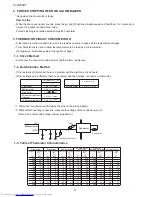
R600A PRECAUTIONS
1.
•Do not use any refrigerant other than R600a.
•Gas leak testers for HFC-134a, CFC-12, HCFC-22, etc., cannot be used.
•A special tool is used for the R600a cycle.
TABLE OF R600A CHARACTERISTICS
2.
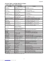
Refrigerant saturated vapor pressure table R600a
(Unit) Temperature: °C, Pressure: kgf/cm abs
Temperature
Pressure
-20
-15
-10
-5
0
10
15
20
25
30
35
40
45
50
5
0.74
1.60
1.34
0.91
1.11
1.91
2.25
2.64
3.08
3.58
4.13
4.74
5.42
7.00
6.17
(Unit)Temperature:°C, Pressure: MPa abs
Temperature
Pressure
-20
-15
-10
-5
0
10
15
20
25
30
35
40
45
50
5
0.073
0.157
0.131
0.089
0.109
0.187
0.221
0.259
0.302
0.351
0.405
0.465
0.532
0.686
0.605
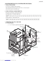
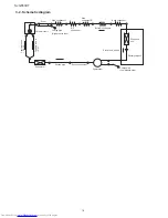
REFRIGERATION CYCLE DIAGRAM
3.
Piping Diagram
3-1.
Evaporator
Charge pipe
Compressor
Discharge pipe
kit
Capillary
tube B
Dryer
Capillary
tube A
Charge pipe
①
②
③
⑤
⑦
⑨
⑬
⑮
⑪
⑧
④
⑯
⑫
⑥
⑩
⑭
⑰
⑳
⑲
⑱
Dew proofing condenser
Extra
cond.
unit kit
←(①~⑳)
Show the order ofthe refrigerant flow
Bottom
condenser
Back
condenser
Suction
connector
Suction
pipe
Valve
turret
Extension
barrel
Side
condenser L
Side
condenser R


